Page 3963 of 4462
STEERING COLUMN PS-15
C
D E
F
H I
J
K L
M A
B
PS
Revision: 2006 December 2006 FX35/FX45
Disassembly and AssemblyNGS000C1
COMPONENTS
SGIA0592E
Page 3964 of 4462
PS-16
STEERING COLUMN
Revision: 2006 December 2006 FX35/FX45
DISASSEMBLY
Disassemble the parts from jacket tube. The parts to be disassembled are shown in the figure.
ASSEMBLY
Refer to PS-15, "COMPONENTS" for tightening torque. Install in the reverse order of disassembly.
1. Meter bracket 2. Jacket tube assembly 3. Upper joint
4. Spring 5. Lock nut 6. Lock block
7. Telescopic lock guide 8. Bush spacer 9. Tilt link assembly
10. Cooler 11. Tilt unit assembly 12. Tilt sensor assembly
13. Connector assembly 14. Clamp 15. Spring
16. Telescopic unit assembly 17. Telescopic sensor assembly
Page 3965 of 4462

POWER STEERING GEAR AND LINKAGE PS-17
C
D E
F
H I
J
K L
M A
B
PS
Revision: 2006 December 2006 FX35/FX45
POWER STEERING GEAR AND LINKAGEPFP:49001
Removal and InstallationNGS000C3
CAUTION:
Spiral cable may snap due to steering operation if steering column is separated from steering gear
assembly. Therefore fix steering wheel with a string to avoid turns.
REMOVAL
1. Set wheels in the straight-ahead position.
2. Remove tires from vehicle with power tool.
3. Remove undercover with power tool.
4. Confirm slit of lower joint fits with the projection on rear cover cap, furthermore marking position on steering gear assembly
nearly fits with the projection on rear cover cap.
5. Remove cotter pin at steering outer socket, then loosen mount- ing nut.
6. Use a ball joint remover (SST) to remove steering outer socket from steering knuckle. Be careful not to damage ball joint boot.
CAUTION:
Tighten temporarily mounting nut to prevent damage to
threads and to prevent ball joint remover (SST) from com-
ing off.
1. Cotter pin 2. Steering gear assembly 3. Washer
4. Clip
SGIA1432E
SGIA0539E
SDIA1434E
Page 3966 of 4462
 from steering gear assembly, then drain fluid from pipings")
PS-18
POWER STEERING GEAR AND LINKAGE
Revision: 2006 December 2006 FX35/FX45
7. Remove oil pipings (high pressure side and low pressure side) from steering gear assembly, then drain fluid from pipings.
8. Remove mounting bolt of steering hydraulic piping bracket from steering gear assembly.
9. Remove mounting bolt (lower side) of lower joint.
10. Remove mounting bolts of steering gear assembly with power tool, and then remove steering gear assembly from vehicle.
INSTALLATION
�Refer to PS-17, "Removal and Installation" for tightening torque. Install in the reverse order of removal.
NOTE:
Refer to component parts location and do not reuse non-reusable parts.
�After removing/installing or replacing steering components, check wheel alignment. Refer to FSU-6,
"Wheel Alignment Inspection" .
�After adjusting wheel alignment, adjust neutral position of steering angle sensor. Refer to BRC-6, "Adjust-
ment of Steering Angle Sensor Neutral Position" .
SGIA0541E
SGIA0545E
SGIA0542E
SGIA0546E
Page 3967 of 4462
POWER STEERING GEAR AND LINKAGE PS-19
C
D E
F
H I
J
K L
M A
B
PS
Revision: 2006 December 2006 FX35/FX45
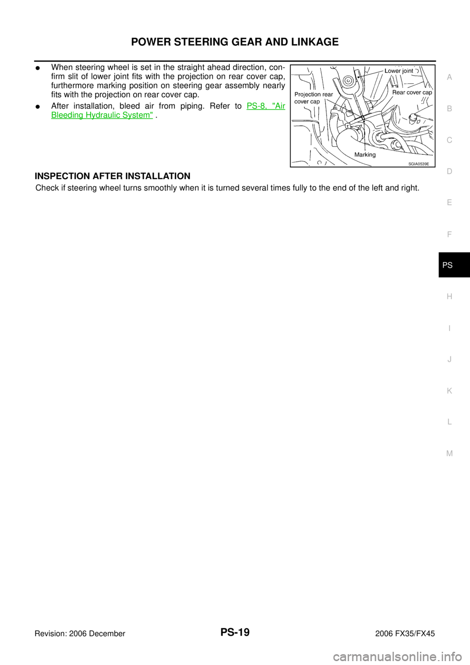
�When steering wheel is set in the straight ahead direction, con-
firm slit of lower joint fits with the projection on rear cover cap,
furthermore marking position on steering gear assembly nearly
fits with the projection on rear cover cap.
�After installation, bleed air from piping. Refer to PS-8, "Air
Bleeding Hydraulic System" .
INSPECTION AFTER INSTALLATION
Check if steering wheel turns smoothly when it is turned several times fully to the end of the left and right.
SGIA0539E
Page 3968 of 4462
PS-20
POWER STEERING GEAR AND LINKAGE
Revision: 2006 December 2006 FX35/FX45
Disassembly and AssemblyNGS000C4
SGIA1433E
Page 3969 of 4462

POWER STEERING GEAR AND LINKAGE PS-21
C
D E
F
H I
J
K L
M A
B
PS
Revision: 2006 December 2006 FX35/FX45
CAUTION:
�Secure steering gear assembly with a vise, using copper
plates or something similar to prevent it from being dam-
aged. Do not grip cylinder with a vise.
�Before performing disassembly, clean steering gear assem-
bly with kerosene. Be careful not to bring any kerosene into
contact with the discharge and return port connectors.
DISASSEMBLY
1. Remove cylinder tubes from gear housing assembly.
2. Remove rear cover cap from gear housing assembly.
3. Measure adjusting screw height from gear housing assembly, then loosen adjusting screw.
CAUTION:
�Do not turn adjusting screw more than twice.
�Replace steering gear assembly when adjusting screw is
removed or more than twice.
4. Use a rear cover wrench (SST) to remove rear cover from sub- gear assembly.
5. Remove O-ring with a flat-bladed screwdriver, and pull out rear cover.
6. Remove sub-gear assembly from gear housing assembly. CAUTION:
In order to protect oil seal from any damage, pull sub-gear
assembly out straightly.
7. Loosen lock nut of outer socket, and remove outer socket.
8. Remove boot clamps of the small diameter side and the large diameter side, then remove boot.
1. Cotter pin 2. Outer socket 3. Boot clamp
4. Boot 5. Inner socket 6. Boot clamp
7. Gear housing assembly 8. Cylinder tubes 9. Rear cover cap
10. Rear cover 11. O-ring 12. Sub-gear assembly
13. Rack oil seal 14. Rack assembly 15. Rack Teflon ring
16. O-ring 17. End cover assembly
SGIA0544E
SGIA0568E
SGIA0728E
SGIA0508E
Page 3970 of 4462

PS-22
POWER STEERING GEAR AND LINKAGE
Revision: 2006 December 2006 FX35/FX45
CAUTION:
When removing boots, be careful not to damage inner socket and gear housing assembly. If they
are damaged, change them to avoid oil leaks.
9. Drill out the clinching part of cylinder outer rim with a 3 mm (0.12 in) drill in 1.5 mm (0.059 in) depth.
10. Remove end cover assembly with a 45 mm (1.77 in) open head (suitable tool).
CAUTION:
Be careful not to damage rack. If it is damaged, replace
rack. Otherwise, oil leaks may result.
11. Pull rack assembly with rack oil seal out of gear housing assem- bly.
CAUTION:
Be careful not to damage cylinder. If it is damaged, replace
gear housing assembly. Otherwise, oil leaks may result.
12. Heat rack Teflon ring to approximately. 40 °C (104 °F) with a
dryer, then remove it and O-ring from rack.
CAUTION:
Be careful not to damage rack. If it is damaged, change to a
new one to avoid oil leaks.
13. Use a taped 29 mm (1.14 in) socket and an extension bar. Remove rack oil seal from gear housing assembly.
CAUTION:
Be careful not to damage gear housing assembly and cylin-
der inner wall. If it is damaged, gear housing assembly
must be replaced. Otherwise, oil leaks will result.
STC0013D
SST081B
SGIA0151E
SGIA0179E