Page 170 of 4462

AT-86
TROUBLE DIAGNOSIS
Revision: 2006 December 2006 FX35/FX45
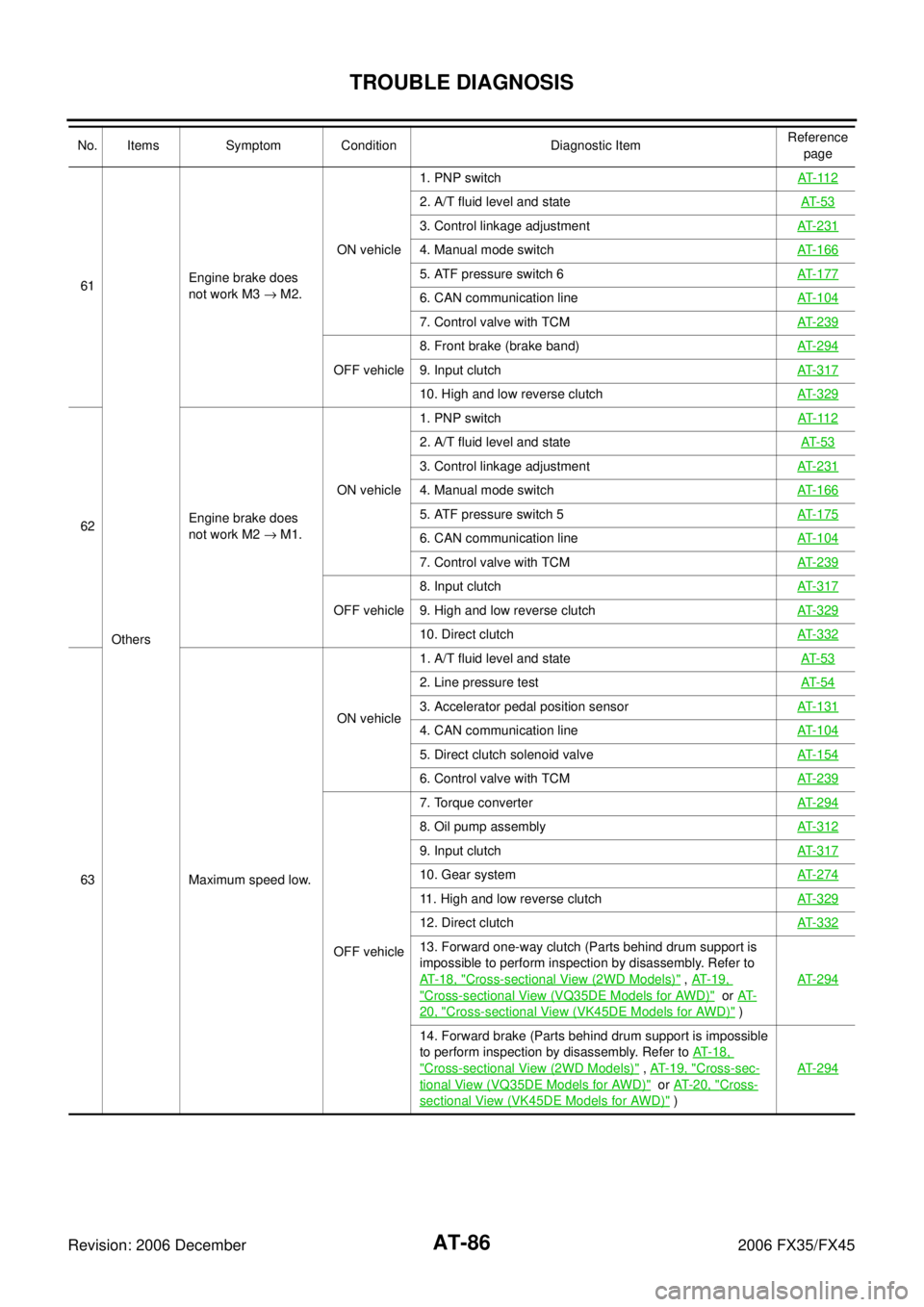
61 Others Engine brake does
not work M3 → M2. ON vehicle 1. PNP switch
AT- 11 2
2. A/T fluid level and state AT- 5 3
3. Control linkage adjustmentAT- 2 3 1
4. Manual mode switchAT- 1 6 6
5. ATF pressure switch 6AT- 1 7 7
6. CAN communication lineAT- 1 0 4
7. Control valve with TCMAT- 2 3 9
OFF vehicle 8. Front brake (brake band)
AT- 2 9 49. Input clutchAT- 3 1 7
10. High and low reverse clutchAT- 3 2 9
62 Engine brake does
not work M2 → M1. ON vehicle 1. PNP switch
AT- 11 2
2. A/T fluid level and state AT- 5 3
3. Control linkage adjustmentAT- 2 3 1
4. Manual mode switchAT- 1 6 6
5. ATF pressure switch 5AT- 1 7 5
6. CAN communication lineAT- 1 0 4
7. Control valve with TCMAT- 2 3 9
OFF vehicle 8. Input clutch
AT- 3 1 79. High and low reverse clutchAT- 3 2 9
10. Direct clutchAT- 3 3 2
63 Maximum speed low. ON vehicle
1. A/T fluid level and state
AT- 5 3
2. Line pressure testAT- 5 4
3. Accelerator pedal position sensorAT- 1 3 1
4. CAN communication lineAT- 1 0 4
5. Direct clutch solenoid valveAT- 1 5 4
6. Control valve with TCMAT- 2 3 9
OFF vehicle 7. Torque converter
AT- 2 9 4
8. Oil pump assemblyAT- 3 1 2
9. Input clutchAT- 3 1 7
10. Gear systemAT- 2 7 4
11. High and low reverse clutchAT- 3 2 9
12. Direct clutchAT- 3 3 2
13. Forward one-way clutch (Parts behind drum support is
impossible to perform inspection by disassembly. Refer to
AT-18, "
Cross-sectional View (2WD Models)" , AT- 1 9 ,
"Cross-sectional View (VQ35DE Models for AWD)" or AT-
20, "Cross-sectional View (VK45DE Models for AWD)" ) AT- 2 9 4
14. Forward brake (Parts behind drum support is impossible
to perform inspection by disassembly. Refer to AT-18,
"Cross-sectional View (2WD Models)" , AT-19, "Cross-sec-
tional View (VQ35DE Models for AWD)" or AT- 2 0 , "Cross-
sectional View (VK45DE Models for AWD)" ) AT- 2 9 4
No. Items Symptom Condition Diagnostic Item
Reference
page
Page 276 of 4462

AT-192
TROUBLE DIAGNOSIS FOR SYMPTOMS
Revision: 2006 December 2006 FX35/FX45
In “N” Position, Vehicle MovesNCS001HM
SYMPTOM:
Vehicle moves forward or backward when selecting “N” position.
DIAGNOSTIC PROCEDURE
1. CHECK PNP SWITCH CIRCUIT
Perform self-diagnosis. Refer to AT- 9 2 , "
SELF-DIAGNOSTIC RESULT MODE" , AT- 1 0 2 , "TCM SELF-DIAG-
NOSTIC PROCEDURE (NO TOOLS)" .
Do the self-diagnostic results indicate PNP switch?
YES >> Check the malfunctioning system. Refer to AT- 11 2 , "DTC P0705 PARK/NEUTRAL POSITION
SWITCH" .
NO >> GO TO 2.
2. CHECK CONTROL LINKAGE
Check the control linkage. Refer to AT- 2 3 1 , "
Checking of A/T Posi-
tion" .
OK or NG
OK >> GO TO 3.
NG >> Adjust control linkage. Refer to AT- 2 3 1 , "
Adjustment of
A/T Position" .
3. CHECK A/T FLUID LEVEL
Check A/T fluid level. Refer to AT- 1 3 , "
Checking A/T Fluid" .
OK or NG
OK >> GO TO 4.
NG >> Refill ATF.
4. CHECK A/T FLUID CONDITION
1. Remove oil pan. Refer to AT- 2 3 9 , "
Control Valve with TCM and A/T Fluid Temperature Sensor 2" .
2. Check A/T fluid condition. Refer to AT- 5 3 , "
A/T Fluid Condition
Check" .
OK or NG
OK >> GO TO 5.
NG >> Check the malfunction items. If any items are damaged,
repair or replace damaged parts. Refer to AT- 6 4 , "
Symp-
tom Chart" (Symptom No.67).
SCIA2119E
SAT638A
SCIA5199E
Page 278 of 4462

AT-194
TROUBLE DIAGNOSIS FOR SYMPTOMS
Revision: 2006 December 2006 FX35/FX45
4. CHECK A/T FLUID LEVEL
Check the A/T fluid level. Refer to AT- 1 3 , "
Checking A/T Fluid" .
OK or NG
OK >> GO TO 5.
NG >> Refill ATF.
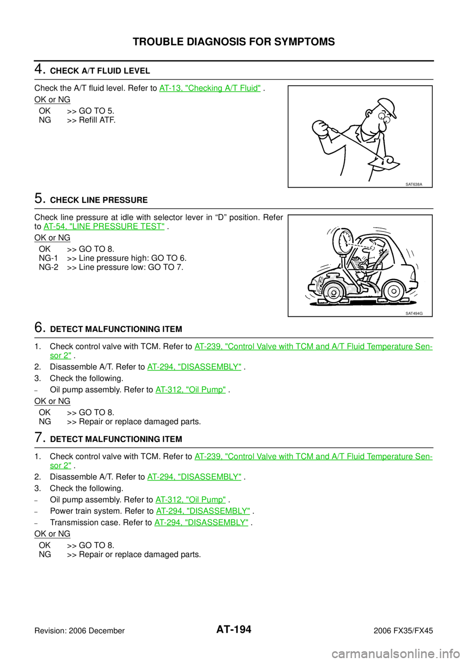
5. CHECK LINE PRESSURE
Check line pressure at idle with selector lever in “D” position. Refer
to AT- 5 4 , "
LINE PRESSURE TEST" .
OK or NG
OK >> GO TO 8.
NG-1 >> Line pressure high: GO TO 6.
NG-2 >> Line pressure low: GO TO 7.
6. DETECT MALFUNCTIONING ITEM
1. Check control valve with TCM. Refer to AT- 2 3 9 , "
Control Valve with TCM and A/T Fluid Temperature Sen-
sor 2" .
2. Disassemble A/T. Refer to AT- 2 9 4 , "
DISASSEMBLY" .
3. Check the following.
–Oil pump assembly. Refer to AT- 3 1 2 , "Oil Pump" .
OK or NG
OK >> GO TO 8.
NG >> Repair or replace damaged parts.
7. DETECT MALFUNCTIONING ITEM
1. Check control valve with TCM. Refer to AT- 2 3 9 , "
Control Valve with TCM and A/T Fluid Temperature Sen-
sor 2" .
2. Disassemble A/T. Refer to AT- 2 9 4 , "
DISASSEMBLY" .
3. Check the following.
–Oil pump assembly. Refer to AT- 3 1 2 , "Oil Pump" .
–Power train system. Refer to AT- 2 9 4 , "DISASSEMBLY" .
–Transmission case. Refer to AT- 2 9 4 , "DISASSEMBLY" .
OK or NG
OK >> GO TO 8.
NG >> Repair or replace damaged parts.
SAT638A
SAT494G
Page 286 of 4462

AT-202
TROUBLE DIAGNOSIS FOR SYMPTOMS
Revision: 2006 December 2006 FX35/FX45
3. CHECK ACCELERATOR POSITION SENSOR
Check accelerator pedal position sensor. Refer to AT- 1 3 1 , "
DTC P1705 THROTTLE POSITION SENSOR"
OK or NG
OK >> GO TO 4.
NG >> Repair or replace accelerator pedal position sensor.
4. CHECK A/T FLUID LEVEL
Check A/T fluid level. Refer to AT- 1 3 , "
Checking A/T Fluid" .
OK or NG
OK >> GO TO 5.
NG >> Refill ATF.
5. CHECK LINE PRESSURE
Check line pressure at the engine stall point. Refer to AT- 5 4 , "
LINE
PRESSURE TEST" .
OK or NG
OK >> GO TO 8.
NG-1 >> Line pressure high: GO TO 6.
NG-2 >> Line pressure low: GO TO 7.
6. DETECT MALFUNCTIONING ITEM
1. Check control valve with TCM. Refer to AT- 2 3 9 , "
Control Valve with TCM and A/T Fluid Temperature Sen-
sor 2" .
2. Disassemble A/T. Refer to AT- 2 9 4 , "
DISASSEMBLY" .
3. Check the following.
–Oil pump assembly. Refer to AT- 3 1 2 , "Oil Pump" .
OK or NG
OK >> GO TO 8.
NG >> Repair or replace damaged parts.
SAT638A
SAT494G
Page 293 of 4462

TROUBLE DIAGNOSIS FOR SYMPTOMS AT-209
D E
F
G H
I
J
K L
M A
B
AT
Revision: 2006 December 2006 FX35/FX45
3. CHECK A/T FLUID LEVEL
Check A/T fluid level. Refer to AT- 1 3 , "
Checking A/T Fluid" .
OK or NG
OK >> GO TO 4.
NG >> Refill ATF.
4. CHECK LINE PRESSURE
Check line pressure at the engine stall point. Refer to AT- 5 4 , "
LINE
PRESSURE TEST" .
OK or NG
OK >> GO TO 7.
NG-1 >> Line pressure high: GO TO 5.
NG-2 >> Line pressure low: GO TO 6.
5. DETECT MALFUNCTIONING ITEM
1. Check control valve with TCM. Refer to AT- 2 3 9 , "
Control Valve with TCM and A/T Fluid Temperature Sen-
sor 2" .
2. Disassemble A/T. Refer to AT- 2 9 4 , "
DISASSEMBLY" .
3. Check the following.
–Oil pump assembly. Refer to AT- 3 1 2 , "Oil Pump" .
OK or NG
OK >> GO TO 7.
NG >> Repair or replace damaged parts.
6. DETECT MALFUNCTIONING ITEM
1. Check control valve with TCM. Refer to AT- 2 3 9 , "
Control Valve with TCM and A/T Fluid Temperature Sen-
sor 2" .
2. Disassemble A/T. Refer to AT- 2 9 4 , "
DISASSEMBLY" .
3. Check the following.
–Oil pump assembly. Refer to AT- 3 1 2 , "Oil Pump" .
–Power train system. Refer to AT- 2 9 4 , "DISASSEMBLY" .
–Transmission case. Refer to AT- 2 9 4 , "DISASSEMBLY" .
OK or NG
OK >> GO TO 7.
NG >> Repair or replace damaged parts.
SAT638A
SAT494G
Page 339 of 4462
ON-VEHICLE SERVICE AT-255
D E
F
G H
I
J
K L
M A
B
AT
Revision: 2006 December 2006 FX35/FX45
INSTALLATION
CAUTION:
After completing installation, check A/T position, A/T fluid leakage and A/F fluid level. Refer to AT- 2 3 1 ,
"Checking of A/T Position" , AT- 1 3 , "Checking A/T Fluid" .
1. As shown in the figure, use a drift to drive rear oil seal into the rear extension until it is flush.
CAUTION:
�Do not reuse rear oil seal.
�Apply ATF to rear oil seal.
2. Install return spring to parking pawl.
3. Install parking pawl (with return spring) and pawl shaft to rear extension.
4. Install parking actuator support to rear extension.
5. Install needle bearing to rear extension.
CAUTION:
Apply petroleum jelly to needle bearing.
SCIA5311E
SCIA2445E
SCIA3424E
SCIA3423E
Page 342 of 4462

AT-258
ON-VEHICLE SERVICE
Revision: 2006 December 2006 FX35/FX45
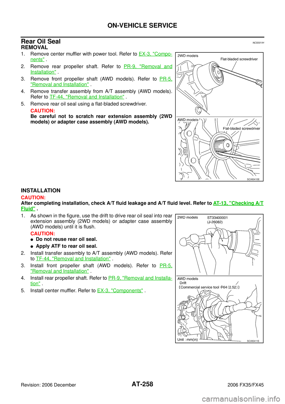
Rear Oil SealNCS001IH
REMOVAL
1. Remove center muffler with power tool. Refer to EX-3, "Compo-
nents" .
2. Remove rear propeller shaft. Refer to PR-9, "
Removal and
Installation" .
3. Remove front propeller shaft (AWD models). Refer to PR-5,
"Removal and Installation" .
4. Remove transfer assembly from A/T assembly (AWD models). Refer to TF-44, "
Removal and Installation" .
5. Remove rear oil seal using a flat-bladed screwdriver. CAUTION:
Be careful not to scratch rear extension assembly (2WD
models) or adapter case assembly (AWD models).
INSTALLATION
CAUTION:
After completing installation, check A/T fluid leakage and A/T fluid level. Refer to AT- 1 3 , "
Checking A/T
Fluid" .
1. As shown in the figure, use the drift to drive rear oil seal into rear extension assembly (2WD models) or adapter case assembly
(AWD models) until it is flush.
CAUTION:
�Do not reuse rear oil seal.
�Apply ATF to rear oil seal.
2. Install transfer assembly to A/T assembly (AWD models). Refer to TF-44, "
Removal and Installation" .
3. Install front propeller shaft (AWD models). Refer to PR-5,
"Removal and Installation" .
4. Install rear propeller shaft. Refer to PR-9, "
Removal and Installa-
tion" .
5. Install center muffler. Refer to EX-3, "
Components" .
SCIA5410E
SCIA5411E
Page 346 of 4462

AT-262
ON-VEHICLE SERVICE
Revision: 2006 December 2006 FX35/FX45
INSTALLATION
CAUTION:
After completing installation, check A/T position, A/T fluid leakage and A/F fluid level. Refer to AT- 2 3 1 ,
"Checking of A/T Position" , AT- 1 3 , "Checking A/T Fluid" .
1. Install revolution sensor in transmission case, and then tighten revolution sensor mounting bolt to the specified torque. Refer to
AT- 2 5 9 , "
COMPONENTS" .
CAUTION:
�Do not subject it to impact by dropping or hitting it.
�Do not disassemble.
�Do not allow metal filings, etc. to get on the sensor's front
edge magnetic area.
�Do not place in an area affected by magnetism.
2. Connect revolution sensor connector.
3. Securely fasten revolution sensor harness with clip.
4. Apply recommended sealant (Genuine Anaerobic Liquid Gasket or equivalent. Refer to GI-48, "
Recommended Chemical Prod-
ucts and Sealants" .) to rear extension assembly as shown in
the figure.
CAUTION:
Completely remove all moisture, oil and old sealant, etc.
from transmission case and rear extension assembly
mounting surfaces.
SCIA3997E
SCIA7524E
SCIA7525E
SCIA5212E