Page 4091 of 4462

REAR LOWER LINK & COIL SPRING RSU-15
C
D
F
G H
I
J
K L
M A
B
RSU
Revision: 2006 December 2006 FX35/FX45
REAR LOWER LINK & COIL SPRINGPFP:551B0
Removal and InstallationNES000I0
REMOVAL
1. Remove tire with power tool.
2. Set jack under rear lower link.
3. Loosen fixing bolt and nut between rear lower link and suspension member, and then remove fixing bolt and nut between rear axle and rear lower link with power tool.
4. Slowly lower jack, then remove upper seat, coil spring and rubber seat from rear lower link.
5. Remove fixing bolt and nut between rear suspension member and rear lower link with power tool.
INSPECTION AFTER REMOVAL
�Check rear lower link, bushing and coil spring for deformation, cracks, and damage. Replace rear lower
link and coil spring if necessary.
INSTALLATION
�Refer to RSU-7, "COMPONENTS" for tightening torque. Install in the reverse order of removal.
CAUTION:
Refer to component parts location and do not reuse non-reusable parts.
�Make sure upper seat is attached as shown in the figure.
NOTE:
Insert bracket tabs (3) and the inside protrusion on upper seat
into each other beforehand as shown in the figure.
�Match up rubber seat indentions and rear lower link grooves and
attach.
NOTE:
Make sure spring is not upside down. The top and bottom are
indicated by paint color.
�Perform final tightening of rear suspension member and axle installation position (rubber bushing) under
unladen conditions with tires on level ground. Check wheel alignment. Refer to RSU-5, "
Wheel Alignment
Inspection" .
SEIA0229E
Page 4093 of 4462

REAR SUSPENSION MEMBER RSU-17
C
D
F
G H
I
J
K L
M A
B
RSU
Revision: 2006 December 2006 FX35/FX45
REAR SUSPENSION MEMBERPFP:55501
Removal and InstallationNES000GF
REMOVAL
1. Remove tires from vehicle with power tool.
2. Remove brake caliper with power tool. Hang it in a place where it will not interfere with work. Refer to BR-
25, "REAR DISC BRAKE" .
NOTE:
Avoid depressing brake pedal while brake caliper is removed.
3. Remove wheel sensor from rear final drive, then remove wheel sensor harness from rear suspension member. Refer to BRC-55, "
WHEEL SENSORS" .
4. Remove height sensor harness from rear suspension member (if equipped).
5. Remove center muffler and main muffler. Refer to EX-3, "
EXHAUST SYSTEM" .
6. Remove stabilizer bar. Refer to RSU-16, "
Removal and Installation" .
7. Remove rear drive shaft. Refer to RAX-9, "
REAR DRIVE SHAFT" .
8. Remove propeller shaft. Refer to PR-7, "
REAR PROPELLER SHAFT" .
9. Remove rear final drive. Refer to RFD-16, "
Removal and Installation" .
10. Separate attachments between parking brake cable and vehicle and rear suspension member. Refer to PB-4, "
PARKING BRAKE CONTROL" .
11. Remove rear lower link and coil spring. Refer to RSU-15, "
Removal and Installation" .
12. Remove fixing bolt in lower side of shock absorber with power tool.
13. Set jack under rear suspension member.
14. Remove fixing bolts and nuts of tunnel stay and member stay with power tool, then remove those parts from vehicle and rear suspension member.
15. Remove fixing bolts and nuts of rear pin stay with power tool and then remove rear pin stay from vehicle and rear suspension member.
16. Slowly lowering jack, then remove rear suspension member, suspension arm, radius rod, front lower link and axle from vehicle as a unit.
17. Remove fixing bolts and nuts with power tool, then remove suspension arm, front lower link, and radius rod from rear suspension member.
INSPECTION AFTER REMOVAL
Check rear suspension member for deformation, cracks, and other damage and replace if necessary.
INSTALLATION
�Refer to RSU-7, "Removal and installation" , for tightening torque. Install in the reverse order of removal.
NOTE:
Refer to component parts location and do not reuse non-reusable parts.
�Perform final tightening of installation position of links (rubber bushing) under unladen conditions with tires
on level ground. Check wheel alignment. Refer to RSU-5, "
Wheel Alignment Inspection" .
�After adjusting wheel alignment, adjust neutral position of steering angle sensor. Refer to BRC-6, "Adjust-
ment of Steering Angle Sensor Neutral Position" .
Page 4310 of 4462
TF-8
NOISE, VIBRATION AND HARSHNESS (NVH) TROUBLESHOOTING
Revision: 2006 December 2006 FX35/FX45
NOISE, VIBRATION AND HARSHNESS (NVH) TROUBLESHOOTINGPFP:00003
NVH Troubleshooting ChartNDS0009R
Use the chart below to help you find the cause of the symptom. The numbers indicate the order of the inspec-
tion. If necessary, repair or replace these parts.
Reference pageTF-9TF-45TF-45TF-51TF-51TF-51
SUSPECTED PARTS
(Possible cause)
TRANSFER FLUID (Level low)
TRANSFER FLUID (Wrong)
TRANSFER FLUID (Level too high)
LIQUID GASKET (Damaged)
OIL SEAL (Worn or damaged)
GEAR (Worn or damaged)
BEARING (Worn or damaged)
TRANSFER CASE (Damaged)
Symptom Noise 1 2 3 3 3
Transfer fluid leakage 4 1 2 2 3
Page 4342 of 4462
TF-40
FRONT OIL SEAL
Revision: 2006 December 2006 FX35/FX45
FRONT OIL SEALPFP:38189
Removal and InstallationNDS000AK
REMOVAL
1. Remove the drain plug to drain the transfer fluid. Refer to TF-9, "Replacement" .
2. Remove the front propeller shaft. Refer to PR-4, "
FRONT PROPELLER SHAFT" .
3. Remove front oil seal using a flat-bladed screwdriver. CAUTION:
Be careful not to damage the front case and front drive
shaft.
INSTALLATION
1. Apply ATF to front oil seal, install it with a drift until the end face of front case.
CAUTION:
�Do not reuse front oil seal.
�When installing, do not incline front oil seal.
2. Install front propeller shaft. Refer to PR-4, "
FRONT PROPEL-
LER SHAFT" .
3. Install transfer fluid, check fluid level and for fluid leakage. Refer to TF-9, "
Inspection" .
SDIA1782E
Tool number : ST27862000 ( — )
SDIA1783E
Page 4344 of 4462
TF-42
REAR OIL SEAL
Revision: 2006 December 2006 FX35/FX45
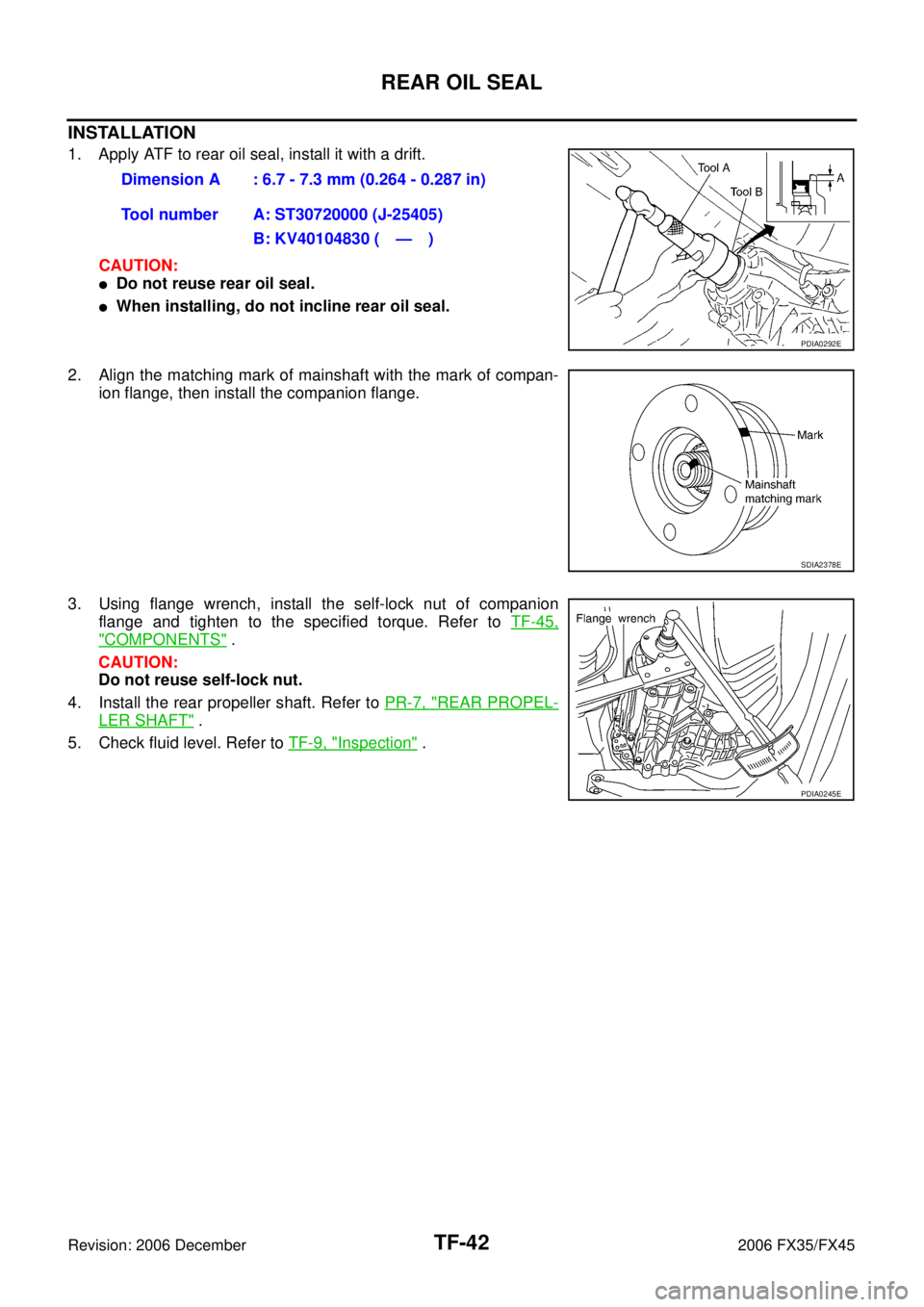
INSTALLATION
1. Apply ATF to rear oil seal, install it with a drift. CAUTION:
�Do not reuse rear oil seal.
�When installing, do not incline rear oil seal.
2. Align the matching mark of mainshaft with the mark of compan- ion flange, then install the companion flange.
3. Using flange wrench, install the self-lock nut of companion flange and tighten to the specified torque. Refer to TF-45,
"COMPONENTS" .
CAUTION:
Do not reuse self-lock nut.
4. Install the rear propeller shaft. Refer to PR-7, "
REAR PROPEL-
LER SHAFT" .
5. Check fluid level. Refer to TF-9, "
Inspection" .
Dimension A : 6.7 - 7.3 mm (0.264 - 0.287 in)
Tool number A: ST30720000 (J-25405) B: KV40104830 ( — )
PDIA0292E
SDIA2378E
PDIA0245E
 TROUBLESHOOTING
Revision: 2006 December 2006 FX35/FX45
NOISE, VIBRATION AND HARSHNESS (NVH) TROUBLESHOOTINGPFP:00003
NVH Troubleshooting ChartNDS0009R
Use the")