Page 4222 of 4462
NIS001VW
1. CHECK KEY SWITCH (WITH CONSULT-II)
With CONSULT-II
Touch “BCM")
SE-84
AUTOMATIC DRIVE POSITIONER
Revision: 2006 December 2006 FX35/FX45
Check Key Switch Circuit (Without Intelligent Key)NIS001VW
1. CHECK KEY SWITCH (WITH CONSULT-II)
With CONSULT-II
Touch “BCM”. With “IGN KEY SW” on the DATA MONITOR, Check ON/OFF operation.
*: Refer to BL-37, "
Data Monitor"
OK or NG
OK >> Key switch circuit is OK.
NG >> GO TO 2.
2. CHECK KEY SWITCH AND KEY LOCK SOLENOID POWER SUPPLY CIRCUIT
1. Turn ignition switch OFF.
2. Disconnect key switch connector.
3. Check voltage between key switch connector M23 terminal 2 and ground.
OK or NG
OK >> GO TO 3.
NG >> Check harness between key switch and fuse.
3. CHECK KEY SWITCH
Check continuity between key switch connector M23 terminal 1 and 2.
OK or NG
OK >> GO TO 4.
NG >> Replace key switch.
Monitor item
[OPERATION or UNIT] Contents
IGN KEY SW
*“ON/
OFF” Key inserted (ON)/key removed (OFF) status judged
from the key-in detection switch is displayed.
PIIA0298E
2 (L/R) – Ground : Battery voltage.
PIIA5092E
Con-
nector Terminal Condition Continuity
M23 1 2 Key is inserted in ignition key cylinder. Yes
Key is removed from ignition key cylinder. No
PIIA6141E
Page 4225 of 4462

Wi")
AUTOMATIC DRIVE POSITIONER SE-87
C
D E
F
G H
J
K L
M A
B
SE
Revision: 2006 December 2006 FX35/FX45
Check Seat Memory Indicator Lamp CircuitNIS001VY
1. CHECK FUNCTION (WITH CONSULT-II)
With CONSULT-II
With “MEMORY SW INDCTR” in ACTIVE TEST, check operation.
OK or NG
OK >> Seat memory indicator lamp circuit is OK.
NG >> GO TO 2.
2. CHECK SEAT MEMORY SWITCH POWER SUPPLY CIRCUIT
1. Turn ignition switch OFF.
2. Disconnect seat memory switch connector.
3. Check voltage between seat memory switch connector D22 ter- minal 5 and ground.
OK or NG
OK >> GO TO 4.
NG >> Repair or replace harness between fuse block (J/B) and seat memory switch.
3. CHECK HARNESS CONTINUITY
1. Disconnect driver seat control unit connector.
2. Check continuity between driver seat control unit connector B152 terminals 23, 36 and seat memory switch connector D22
terminals 6, 7.
3. Check continuity between driver seat control unit connector B152 terminals 23, 36 and ground.
OK or NG
OK >> GO TO 5.
NG >> Repair or replace harness between driver seat control unit and seat memory switch.
Test item Description
MEMORY SW
INDCTR The memory switch indicator is lit by receiving the drive signal.
PIIA0319E
5 (R) – Ground : Battery voltage
PIIA4595E
23 (Y/W) – 6 (PU) : Continuity should exist.
36 (Y/G) – 7 (L) : Continuity should exist.
23 (Y/W) – Ground : Continuity should not exist.
36 (Y/G) – Ground : Continuity should not exist.
PIIB8599E
Page 4228 of 4462

SE-90
AUTOMATIC DRIVE POSITIONER
Revision: 2006 December 2006 FX35/FX45
Check Lumbar Support CircuitNIS001W0
1. CHECK LUMBAR SUPPORT SWITCH
1. Turn ignition switch OFF.
2. Disconnect lumbar support switch connector.
3. Check voltage between lumbar support switch connector B158 terminal 1 and ground.
OK or NG
OK >> GO TO 2.
NG >> Repair or replace harness between fuse block (J/B) and lumbar support switch.
2. CHECK LUMBAR SUPPORT SWITCH
Lumbar support switch operate, check continuity lumbar support switch connector B158 terminal 31, 32 and 1,
16B.
OK or NG
OK >> GO TO 3.
NG >> Replace lumbar support switch.
3. CHECK LUMBAR SUPPORT MOTOR HARNESS
1. Disconnect lumbar support motor connector.
2. Check continuity between lumbar support switch connector B158 terminal 31, 32 and lumbar support motor connector B172
terminal 31, 32.
3. Check continuity between lumbar support switch connector B158 terminal 31, 32 and ground.
OK or NG
OK >> GO TO 4.
NG >> Repair or replace harness between lumbar support switch and lumbar support motor. 1 (R) – Ground: : Battery voltage
PIIB8600E
Con-
nector Terminal Lumbar support switch
condition Continuity
B158 31
1 BACKWARD Yes
16B Other than above No
32 1FORWARD Yes
16B Other than above No
PIIB8601E
31 (W) − 31 (W) : Continuity should exist.
32 (L) − 32 (L) : Continuity should exist.
31 (W) − Ground : Continuity should not exist.
32 (L) − Ground : Continuity should not exist.
PIIB8602E
Page 4284 of 4462

SRS-36
TROUBLE DIAGNOSIS
Revision: 2006 December 2006 FX35/FX45
Trouble Diagnosis: “AIR BAG” Warning Lamp Does Not Turn OFFNHS0007J
DIAGNOSTIC PROCEDURE 7
1. CHECK THE DEPLOYMENT OF AIR BAG MODULE
Is air bag module deployed?
YES or NO
YES >> Refer to SRS-50, "COLLISION DIAGNOSIS" .
NO >> GO TO 2.
2. CHECK THE AIR BAG FUSE
Check 10A fuse [No. 13, located in fuse block (J/B)].
Refer to PG-3, "
POWER SUPPLY ROUTING CIRCUIT" .
OK or NG
OK >> GO TO 4.
NG >> GO TO 3.
3. CHECK AIR BAG FUSE AGAIN
Replace “AIR BAG” fuse and turn ignition switch ON.
Does the
“AIR BAG” fuse blow again?
YES >> Repair or replace main harness.
NO >> INSPECTION END
4. CHECK DIAGNOSIS SENSOR UNIT
Connect CONSULT-II and touch “START”.
Is “AIR BAG” displayed on CONSULT-II?
YES or NO
YES >> GO TO 5.
NO >> Visually check the wiring harness connection of diagno- sis sensor unit. If the harness connection check result is
OK, replace diagnosis sensor unit.
5. CHECK HARNESS CONNECTION
Is harness connection between warning lamp and diagnosis sensor unit OK?
OK or NG
OK >> Replace diagnosis sensor unit.
NG >> Connect “AIR BAG” warning lamp and diagnosis sensor unit connector properly. If “AIR BAG” warning lamp still does not go off, replace harness.
BCIA0030E
Page 4285 of 4462
TROUBLE DIAGNOSIS SRS-37
C
D E
F
G
I
J
K L
M A
B
SRS
Revision: 2006 December 2006 FX35/FX45
Trouble Diagnosis: “AIR BAG” Warning Lamp Does Not Turn ONNHS0007K
DIAGNOSTIC PROCEDURE 8
1. CHECK METER FUSE
Check 10A fuse [No. 14, located in fuse block (J/B)].
Refer to PG-3, "
POWER SUPPLY ROUTING CIRCUIT" .
OK or NG
OK >> GO TO 3.
NG >> GO TO 2.
2. CHECK METER FUSE AGAIN
Replace 10A fuse [No. 14, located in fuse block (J/B)] and turn ignition switch ON.
Does the meter fuse blow again?
YES >> Repair or replace the related harness.
NO >> INSPECTION END
3. CHECK HARNESS CONNECTION BETWEEN DIAGNOSIS SENSOR UNIT AND COMBINATION
METER
Disconnect diagnosis sensor unit connector and turn ignition switch ON.
Does “AIR BAG” warning lamp turn on?
YES or NO
YES >> Replace diagnosis sensor unit.
NO >> Replace combination meter assembly.
Page 4286 of 4462
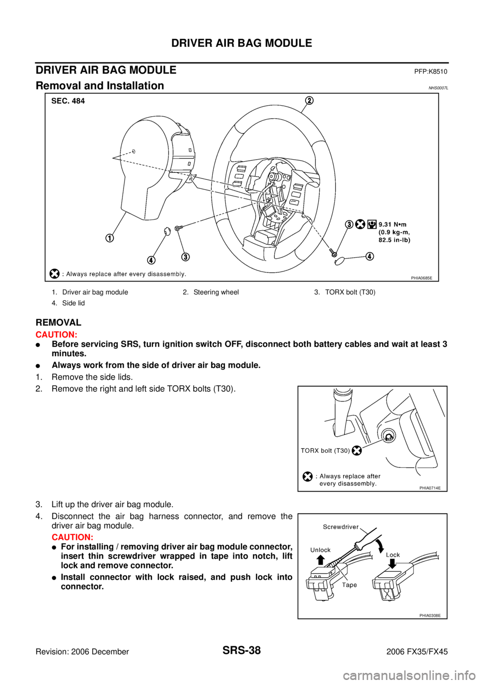
SRS-38
DRIVER AIR BAG MODULE
Revision: 2006 December 2006 FX35/FX45
DRIVER AIR BAG MODULEPFP:K8510
Removal and InstallationNHS0007L
REMOVAL
CAUTION:
�Before servicing SRS, turn ignition switch OFF, disconnect both battery cables and wait at least 3
minutes.
�Always work from the side of driver air bag module.
1. Remove the side lids.
2. Remove the right and left side TORX bolts (T30).
3. Lift up the driver air bag module.
4. Disconnect the air bag harness connector, and remove the driver air bag module.
CAUTION:
�For installing / removing driver air bag module connector,
insert thin screwdriver wrapped in tape into notch, lift
lock and remove connector.
�Install connector with lock raised, and push lock into
connector.
PHIA0685E
1. Driver air bag module 2. Steering wheel 3. TORX bolt (T30)
4. Side lid
PHIA0714E
PHIA0308E
Page 4328 of 4462

TF-26
TROUBLE DIAGNOSIS FOR SYSTEM
Revision: 2006 December 2006 FX35/FX45
TROUBLE DIAGNOSIS FOR SYSTEMPFP:00000
Power Supply Circuit for AWD Control UnitNDS000A6
CONSULT-II REFERENCE VALUE IN DATA MONITOR MODE
Data are reference value.
DIAGNOSTIC PROCEDURE
1. CHECK POWER SUPPLY
1. Turn ignition switch “OFF”.
2. Disconnect AWD control unit harness connector.
3. Turn ignition switch “ON”. (Do not start engine.)
4. Check voltage between AWD control unit harness connector ter- minals and ground.
5. Turn ignition switch “OFF”.
6. Check voltage between AWD control unit harness connector ter- minals and ground.
OK or NG
OK >> GO TO 2.
NG >> Check the following. If any items are damaged, repair or replace damaged parts.
�10A fuse [No. 12 or 21, located in the fuse block (J/B)]
�Harness for short or open between battery and AWD control unit harness connector terminal 9
�Harness for short or open between ignition switch and AWD control unit harness connector ter-
minal 7
�Ignition switch. Refer to PG-3, "POWER SUPPLY ROUTING CIRCUIT" .
Monitored item [Unit] Condition Display value (Approx.)
BATTERY VOLT [V] Ignition switch: ON Battery voltage
Connector Terminal Voltage (Approx.)
M92 7 - Ground
Battery voltage
9 - Ground
SDIA2319E
Connector Terminal Voltage (Approx.)
M92 7 - Ground 0V
9 - Ground Battery voltage
SDIA2320E
Page 4331 of 4462

TROUBLE DIAGNOSIS FOR SYSTEM TF-29
C E F
G H
I
J
K L
M A
B
TF
Revision: 2006 December 2006 FX35/FX45
1. CHECK AWD SOLENOID SIGNAL
With CONSULT-II
1. Start engine.
2. Select “DATA MONITOR” mode for “ALL MODE AWD/4WD” with CONSULT-II.
3. Read out the value of “ETS SOLENOID”.
*: The values are changed by throttle opening and engine speed.
OK or NG
OK >> GO TO 6.
NG >> GO TO 2.
2. CHECK POWER SUPPLY
1. Turn ignition switch “OFF”.
2. Disconnect AWD control unit harness connector.
3. Turn ignition switch “ON”. (Do not start engine.)
4. Check voltage between AWD control unit harness connector ter- minal 9 and ground.
OK or NG
OK >> GO TO 3.
NG >> Check the following. If any items are damaged, repair or replace damaged parts.
�10A fuse [No. 21, located in the fuse block (J/B)]
�Harness for short or open between battery and AWD
control unit harness connector terminal 9
3. CHECK AWD SOLENOID CIRCUIT
1. Turn ignition switch “OFF”.
2. Disconnect AWD control unit harness connector.
3. Check resistance between AWD control unit harness connector terminals 1 and 2.
OK or NG
OK >> GO TO 6.
NG >> GO TO 4.
Condition Display value
Engine running At idle speed Approx. 0.000A
When depressing accelerator
pedal Approx. 0.000 - 2.400A*
SDIA1885E
Connector Terminal Voltage (Approx.)
M92 9 - Ground Battery voltage
SDIA1884E
Connector Terminal Resistance (Approx.)M92 1 - 2 (Ground) 2.45 Ω
SDIA1928E