Page 3085 of 4462
EXHAUST SYSTEM EX-3
C
D E
F
G H
I
J
K L
M A
EX
Revision: 2006 December 2006 FX35/FX45
EXHAUST SYSTEMPFP:20100
Checking Exhaust SystemNBS004IN
Check exhaust pipes, muffler and mounting for improper attachment,
leaks, cracks, damage or deterioration.
�If anything is found, repair or replace damaged parts.
ComponentsNBS004IO
CAUTION:
�Be sure to use genuine exhaust system parts or equivalents which are specially designed for heat
resistance, corrosion resistance, and shape.
�Perform the operation with the exhaust system fully cooled down because the system will be hot
just after engine stops.
�Be careful not to cut your hand on the heat insulator edge.
VQ35DE
SMA211A
PBIC1583E
1. Main muffler 2. Mounting rubber 3. Main muffler mounting bracket
4. Mounting rubber 5. Center muffler 6. Gasket
7. Exhaust front tube 8. Gasket 9. Collar
Page 3086 of 4462
EX-4
EXHAUST SYSTEM
Revision: 2006 December 2006 FX35/FX45
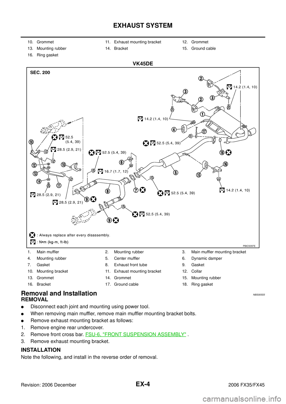
VK45DE
Removal and InstallationNBS005S5
REMOVAL
�Disconnect each joint and mounting using power tool.
�When removing main muffler, remove main muffler mounting bracket bolts.
�Remove exhaust mounting bracket as follows:
1. Remove engine rear undercover.
2. Remove front cross bar. FSU-6, "
FRONT SUSPENSION ASSEMBLY" .
3. Remove exhaust mounting bracket.
INSTALLATION
Note the following, and install in the reverse order of removal.
10. Grommet 11. Exhaust mounting bracket 12. Grommet
13. Mounting rubber 14. Bracket 15. Ground cable
16. Ring gasket
PBIC5097E
1. Main muffler 2. Mounting rubber 3. Main muffler mounting bracket
4. Mounting rubber 5. Center muffler 6. Dynamic damper
7. Gasket 8. Exhaust front tube 9. Gasket
10. Mounting bracket 11. Exhaust mounting bracket 12. Collar
13. Grommet 14. Grommet 15. Mounting rubber
16. Bracket 17. Ground cable 18. Ring gasket
Page 3087 of 4462

EXHAUST SYSTEM EX-5
C
D E
F
G H
I
J
K L
M A
EX
Revision: 2006 December 2006 FX35/FX45
�Tighten main muffler mounting bracket bolts in numerical order
as shown in the figure.
CAUTION:
�Always replace exhaust tube gaskets with new ones when reassembling.
�If heat insulator is badly deformed, repair or replace it. If deposits such as mud pile up on the heat
insulator, remove them.
�When installing heat insulator avoid large gaps or interference between heat insulator and each
exhaust pipe.
�Remove deposits from the sealing surface of each connection. Connect them securely to avoid
gases leakage.
�Temporarily tighten mounting nuts on the exhaust manifold side and mounting bolts on the vehi-
cle side. Check each part for unusual interference, and then tighten them to the specified torque.
�When installing each mounting rubber, avoid twisting or unusual extension in up/down and right/
left directions.
INSPECTION AFTER INSTALLATION
�Make sure clearance between tail tube and bumper is even.
�With engine running, check exhaust tube joints for gas leakage and unusual noises.
�Check to ensure that mounting brackets and mounting rubbers are installed properly and free from undue
stress. Improper installation could result in excessive noise and vibration.
PBIC1049E
Page 3088 of 4462
EX-6
EXHAUST SYSTEM
Revision: 2006 December 2006 FX35/FX45
Page 3127 of 4462
NDS000BC
COM")
FRONT FINAL DRIVE ASSEMBLY FFD-13
C E F
G H
I
J
K L
M A
B
FFD
Revision: 2006 December 2006 FX35/FX45
FRONT FINAL DRIVE ASSEMBLYPFP:38500
Removal and Installation (VQ35DE Models)NDS000BC
COMPONENTS
REMOVAL
1. Remove three engine mounting bracket upper bolts. Refer to EM-118, "Components (AWD Models)" .
2. Remove three way catalyst (right bank). Refer to EM-26, "
EXHAUST MANIFOLD AND THREE WAY CAT-
ALYST" .
3. Remove stabilizer assembly with power tool. Refer to FSU-16, "
STABILIZER BAR" .
4. Remove steering gearbox mounting bolts with power tool. Refer to PS-17, "
POWER STEERING GEAR
AND LINKAGE" .
5. Remove front drive shaft both. Refer to FA X - 1 2 , "
FRONT DRIVE SHAFT" .
6. Remove side shaft assembly.
7. Remove front propeller shaft. Refer to PR-4, "
FRONT PROPELLER SHAFT" .
8. Remove front suspension member with power tool. Refer to FSU-17, "
FRONT SUSPENSION MEMBER" .
9. Remove breather hose and tube.
10. Remove mounting bolts and remove front final drive assembly from the vehicle.
INSTALLATION
Note the following, and installation is in the reverse order of removal.
�Refer to FFD-13, "COMPONENTS" about each tightening torque.
�When installing the side shaft, apply multi-purpose grease to contact surface of side shaft and side shaft
oil seal.
1. Front final drive assembly 2. Side shaft 3. Bushing
4. Front propeller shaft 5. Breather hose 6. Breather tube
7. Breather connector 8. Engine mounting bracket 9. Insulator
Refer to GI-11, "
Components" , for the symbols in the figure.
PDIA0789J
Page 3129 of 4462
NDS000BD
COMPONENTS
REMOVAL
1. Remove three way")
FRONT FINAL DRIVE ASSEMBLY FFD-15
C E F
G H
I
J
K L
M A
B
FFD
Revision: 2006 December 2006 FX35/FX45
Removal and Installation (VK45DE Models)NDS000BD
COMPONENTS
REMOVAL
1. Remove three way catalyst (right bank). Refer to EM-183, "EXHAUST MANIFOLD AND THREE WAY
CATALYST" .
2. Remove stabilizer assembly with power tool. Refer to FSU-16, "
STABILIZER BAR" .
3. Remove steering gearbox mounting bolts with power tool. Refer to PS-17, "
POWER STEERING GEAR
AND LINKAGE" .
4. Remove front drive shaft both. Refer to FA X - 1 2 , "
FRONT DRIVE SHAFT" .
5. Remove side shaft assembly.
6. Remove front propeller shaft. Refer to PR-4, "
FRONT PROPELLER SHAFT" .
7. Remove front suspension member with power tool. Refer to FSU-17, "
FRONT SUSPENSION MEMBER" .
8. Remove engine wire harness clamp bolts from front final drive.
9. Remove breather hose and tube.
10. Remove mounting bolts and remove front final drive assembly from the vehicle.
INSTALLATION
Note the following, and installation is in the reverse order of removal.
�Refer to FFD-15, "COMPONENTS" about each tightening torque.
�When installing side shaft, apply multi-purpose grease to contact surface of side shaft and side shaft oil
seal.
1. Front final drive assembly 2. Side shaft 3. Bushing
4. Front propeller shaft 5. Breather tube 6. Breather hose
7. Breather connector 8. Harness bracket
PDIA0659E
Page 3164 of 4462

FL-10
FUEL TANK
Revision: 2006 December 2006 FX35/FX45
FUEL TANKPFP:17202
ComponentsNBS004IK
Removal and InstallationNBS005S4
REMOVAL
WARNING:
Be sure to read “General Precautions” when working on the fuel system. Refer to FL-3, "
General Pre-
cautions" .
�Drain fuel from fuel tank if necessary. Refer to FL-4, "REMOVAL" .
�Perform work on level place.
1. Perform steps 2 to 7 of “REMOVAL” in “ FUEL LEVEL SENSOR UNIT, FUEL FILTER AND FUEL PUMP ASSEMBLY” on main and sub fuel level sensor units. Refer to FL-4, "
REMOVAL" .
2. Remove tunnel stay. Refer to RSU-5, "
REAR SUSPENSION ASSEMBLY" .
3. Remove exhaust front tube, center muffler and main muffler. Refer to EX-3, "
EXHAUST SYSTEM" .
4. Remove insulator.
5. Remove propeller shaft. Refer to PR-7, "
REAR PROPELLER SHAFT" .
6. Remove parking rear brake cables. Refer to PB-4, "
PARKING BRAKE CONTROL" .
7. Remove rear suspension assembly. Refer to RSU-5, "
REAR SUSPENSION ASSEMBLY" .
8. Remove fuel tank protector.
1. Grommet 2. Fuel filler cap 3. Clip
4. Fuel filler tube protector 5. Fuel tank mounting band 6. Fuel tank protector
7. Insulator 8. Fuel tank 9. Vent tube
10. Vent hose 11. EVAP hose 12. Vent hose
13. Fuel filler hose 14. Fuel filler tube
PBIC1580E
Page 3188 of 4462

GI-4
PRECAUTIONS
Revision: 2006 December 2006 FX35/FX45
Precautions for Procedures without Cowl Top CoverNAS0005Z
When performing the procedure after removing cowl top cover, cover
the lower end of windshield with urethane, etc.
General PrecautionsNAS00060
�Do not operate the engine for an extended period of time without
proper exhaust ventilation.
Keep the work area well ventilated and free of any flammable
materials. Special care should be taken when handling any flam-
mable or poisonous materials, such as gasoline, refrigerant gas,
etc. When working in a pit or other enclosed area, be sure to
properly ventilate the area before working with hazardous mate-
rials.
Do not smoke while working on the vehicle.
�Before jacking up the vehicle, apply wheel chocks or other tire
blocks to the wheels to prevent the vehicle from moving. After
jacking up the vehicle, support the vehicle weight with safety
stands at the points designated for proper lifting before working
on the vehicle.
These operations should be done on a level surface.
�When removing a heavy component such as the engine or tran-
saxle/transmission, be careful not to lose your balance and drop
them. Also, do not allow them to strike adjacent parts, especially
the brake tubes and master cylinder.
�Before starting repairs which do not require battery power:
Turn off ignition switch.
Disconnect the negative battery terminal.
�If the battery terminals are disconnected, recorded memory of
radio and each control unit is erased.
�Battery posts, terminals and related accessories contain lead
and lead compounds. Wash hands after handling.
PIIB3706J
SGI285
SGI231
SEF289H