Page 722 of 4462
AV-116
NAVIGATION SYSTEM
Revision: 2006 December 2006 FX35/FX45
32 (L) Ground Communication
signal (+) Input/
Output ON —
33 — Shield — — — —
34 (P) Ground Communication
signal (–) Input/
Output ON —
36 (PU) Ground Communication signal
(DCU-DSP) Output ON —
37 — Shield — — — —
38 (LG) Ground Communication signal
(DSP-DCU) Input ON —
39 — Shield — — — —
40 (LG) Ground Communication signal
(DCU-AUD) Output ON
Operate audio volume
switch
41 — Shield — — — —
42 (PU) Ground Communication signal
(AUD-DCU) Input ON Operate audio volume
switch
Te r m i n a l
(Wire color) Item Signal
input/
output Condition
Reference value
+– Ignition
switch Operation
SKIB7378E
SKIB7379E
SKIB3607E
SKIB3606E
SKIB3607E
SKIB3606E
Page 723 of 4462

NAVIGATION SYSTEM AV-117
C
D E
F
G H
I
J
L
M A
B
AV
Revision: 2006 December 2006 FX35/FX45
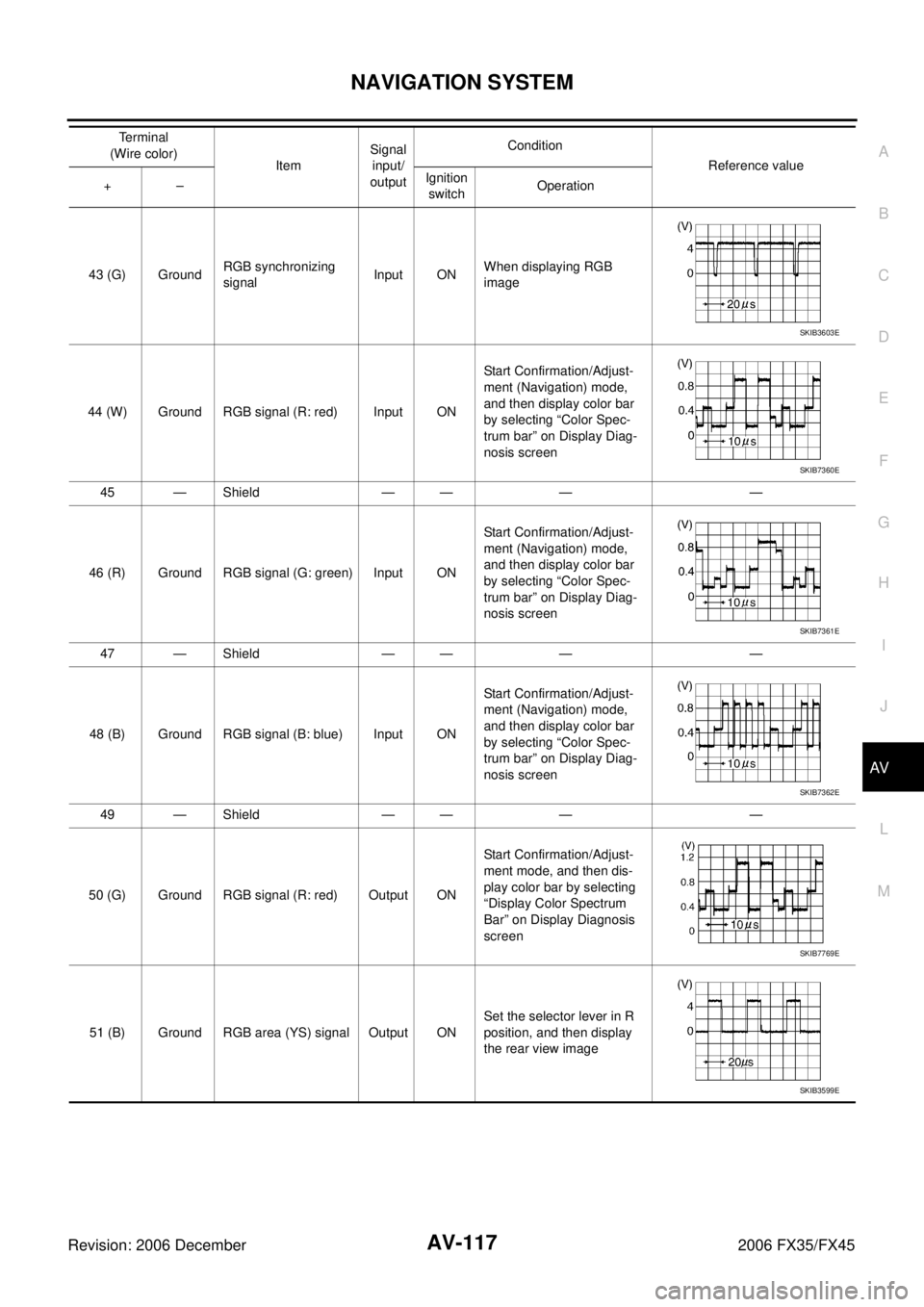
43 (G) Ground RGB synchronizing
signal Input ON When displaying RGB
image
44 (W) Ground RGB signal (R: red) Input ON Start Confirmation/Adjust-
ment (Navigation) mode,
and then display color bar
by selecting “Color Spec-
trum bar” on Display Diag-
nosis screen
45 — Shield — — — —
46 (R) Ground RGB signal (G: green) Input ON Start Confirmation/Adjust-
ment (Navigation) mode,
and then display color bar
by selecting “Color Spec-
trum bar” on Display Diag-
nosis screen
47 — Shield — — — —
48 (B) Ground RGB signal (B: blue) Input ON Start Confirmation/Adjust-
ment (Navigation) mode,
and then display color bar
by selecting “Color Spec-
trum bar” on Display Diag-
nosis screen
49 — Shield — — — —
50 (G) Ground RGB signal (R: red) Output ON Start Confirmation/Adjust-
ment mode, and then dis-
play color bar by selecting
“Display Color Spectrum
Bar” on Display Diagnosis
screen
51 (B) Ground RGB area (YS) signal Output ON Set the selector lever in R
position, and then display
the rear view image
Terminal
(Wire color) Item Signal
input/
output Condition
Reference value
+– Ignition
switch Operation
SKIB3603E
SKIB7360E
SKIB7361E
SKIB7362E
SKIB7769E
SKIB3599E
Page 724 of 4462
AV-118
NAVIGATION SYSTEM
Revision: 2006 December 2006 FX35/FX45
52 (Y) Ground RGB signal (G: green) Output ON Start Confirmation/Adjust-
ment mode, and then dis-
play color bar by selecting
“Display Color Spectrum
Bar” on Display Diagnosis
screen
53 (W) Ground Vertical
synchronizing (VP)
signal Input ON —
54 (L) Ground RGB signal (B: blue) Output ON Start Confirmation/Adjust-
ment mode, and then dis-
play color bar by selecting
“Display Color Spectrum
Bar” on Display Diagnosis
screen
55 (R) Ground Horizontal
synchronizing (HP)
signal Input ON —
56 (G) Ground RGB synchronizing
signal Output ON
When displaying RGB
image
Te r m i n a l
(Wire color) Item Signal
input/
output Condition
Reference value
+– Ignition
switch Operation
SKIB7770E
SKIB3598E
SKIB7771E
SKIB3601E
SKIB3603E
Page 725 of 4462

NAVIGATION SYSTEM AV-119
C
D E
F
G H
I
J
L
M A
B
AV
Revision: 2006 December 2006 FX35/FX45
Terminals and Reference Value for DisplayNKS003KA
Terminal
(Wire color) Item Signal
input/
output Condition
Reference value
+– Ignition
switch Operation
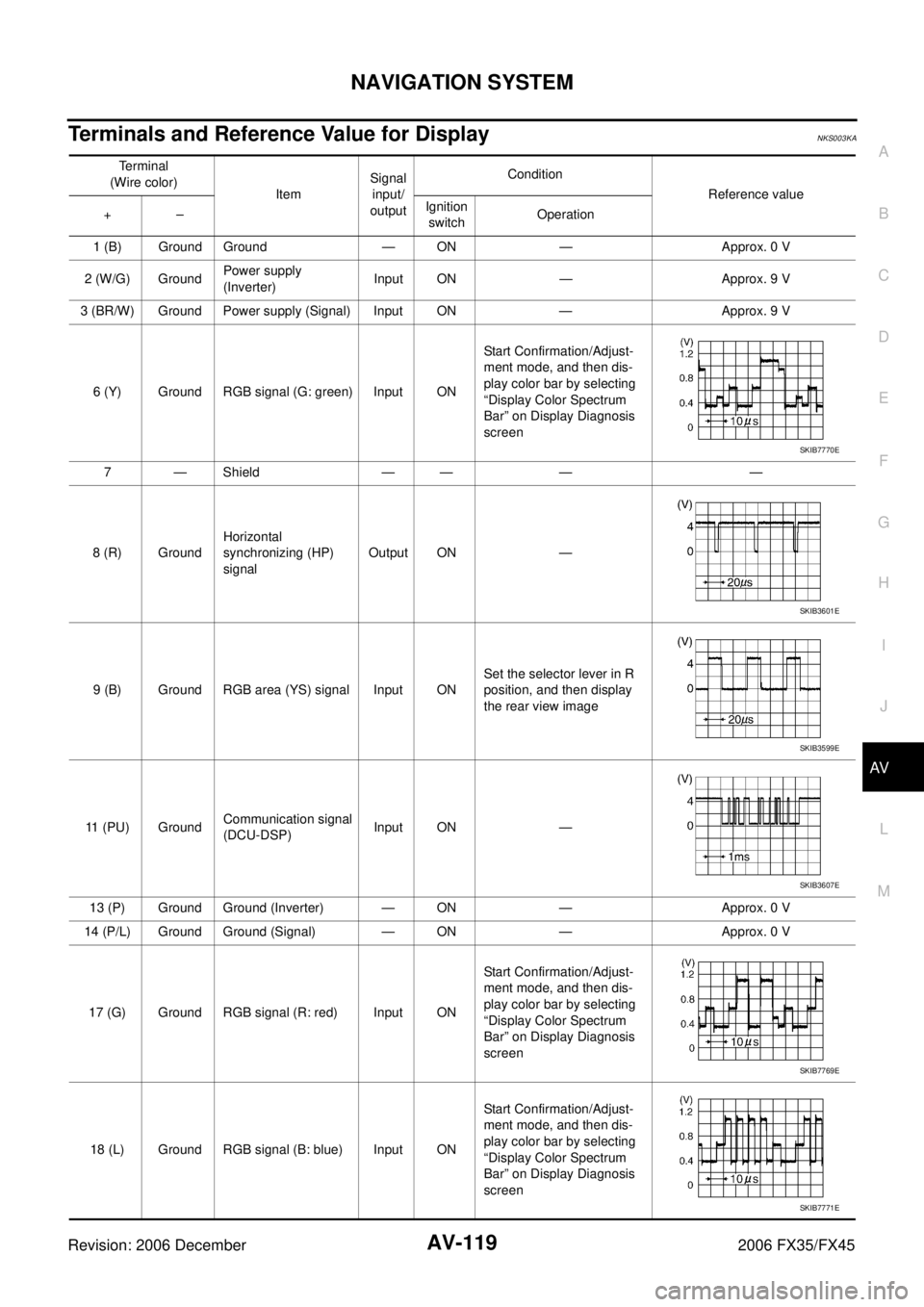
1 (B) Ground Ground — ON — Approx. 0 V
2 (W/G) Ground Power supply
(Inverter) Input ON — Approx. 9 V
3 (BR/W) Ground Power supply (Signal) Input ON — Approx. 9 V
6 (Y) Ground RGB signal (G: green) Input ON Start Confirmation/Adjust-
ment mode, and then dis-
play color bar by selecting
“Display Color Spectrum
Bar” on Display Diagnosis
screen
7 — Shield — — — —
8 (R) Ground Horizontal
synchronizing (HP)
signal Output ON —
9 (B) Ground RGB area (YS) signal Input ON Set the selector lever in R
position, and then display
the rear view image
11 (PU) Ground Communication signal
(DCU-DSP) Input ON —
13 (P) Ground Ground (Inverter) — ON — Approx. 0 V
14 (P/L) Ground Ground (Signal) — ON — Approx. 0 V
17 (G) Ground RGB signal (R: red) Input ON Start Confirmation/Adjust-
ment mode, and then dis-
play color bar by selecting
“Display Color Spectrum
Bar” on Display Diagnosis
screen
18 (L) Ground RGB signal (B: blue) Input ON Start Confirmation/Adjust-
ment mode, and then dis-
play color bar by selecting
“Display Color Spectrum
Bar” on Display Diagnosis
screen
SKIB7770E
SKIB3601E
SKIB3599E
SKIB3607E
SKIB7769E
SKIB7771E
Page 726 of 4462
AV-120
NAVIGATION SYSTEM
Revision: 2006 December 2006 FX35/FX45
19 (G) Ground RGB synchronizing
signal Input ON When displaying RGB
image
20 (W) Ground Vertical
synchronizing (VP)
signal Output ON —
21 — Shield — — — —
22 (LG) Ground Communication signal
(DSP-DCU) Output ON —
23 — Shield — — — — Te r m i n a l
(Wire color) Item Signal
input/
output Condition
Reference value
+– Ignition
switch Operation
SKIB3603E
SKIB3598E
SKIB3606E
Page 727 of 4462
NAVIGATION SYSTEM AV-121
C
D E
F
G H
I
J
L
M A
B
AV
Revision: 2006 December 2006 FX35/FX45
Terminals and Reference Value for A/C and AV SwitchNKS003KB
Terminal
(Wire color) Item Signal
input/
output Condition
Reference value
+– Ignition
switch Operation
1 (W/L) Ground Battery power supply Input OFF — Battery voltage 2 (LG) Ground ACC power supply Input ACC — Battery voltage
5 (B) Ground Ground — ON — Approx. 0 V
6 (PU) Ground Communication
signal (+) Input/
Output ON —
7 — Shield — — — —
8 (LG) Ground Communication
signal (–) Input/
Output ON —
SKIB7378E
SKIB7379E
Page 730 of 4462

AV-124
NAVIGATION SYSTEM
Revision: 2006 December 2006 FX35/FX45
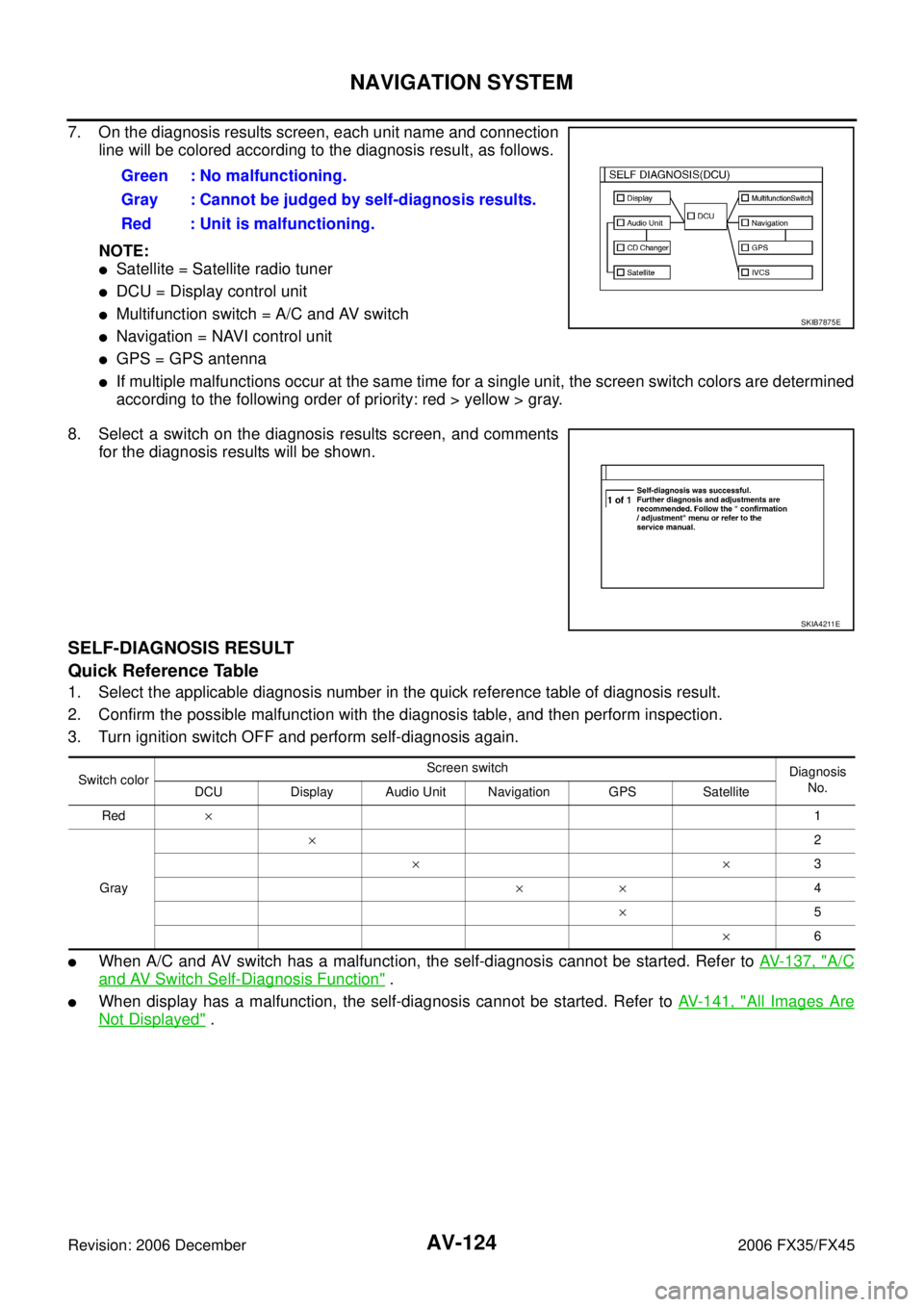
7. On the diagnosis results screen, each unit name and connection line will be colored according to the diagnosis result, as follows.
NOTE:
�Satellite = Satellite radio tuner
�DCU = Display control unit
�Multifunction switch = A/C and AV switch
�Navigation = NAVI control unit
�GPS = GPS antenna
�If multiple malfunctions occur at the same time for a single unit, the screen switch colors are determined
according to the following order of priority: red > yellow > gray.
8. Select a switch on the diagnosis results screen, and comments for the diagnosis results will be shown.
SELF-DIAGNOSIS RESULT
Quick Reference Table
1. Select the applicable diagnosis number in the quick reference table of diagnosis result.
2. Confirm the possible malfunction with the diagnosis table, and then perform inspection.
3. Turn ignition switch OFF and perform self-diagnosis again.
�When A/C and AV switch has a malfunction, the self-diagnosis cannot be started. Refer to AV- 1 3 7 , "A/C
and AV Switch Self-Diagnosis Function" .
�When display has a malfunction, the self-diagnosis cannot be started. Refer to AV-141, "All Images Are
Not Displayed" .
Green : No malfunctioning.
Gray : Cannot be judged by self-diagnosis results.
Red : Unit is malfunctioning.
SKIB7875E
SKIA4211E
Switch color Screen switch
Diagnosis
No.
DCU Display Audio Unit Navigation GPS Satellite
Red × 1
Gray ×
2
×× 3
×× 4
× 5
× 6
Page 736 of 4462

AV-130
NAVIGATION SYSTEM
Revision: 2006 December 2006 FX35/FX45
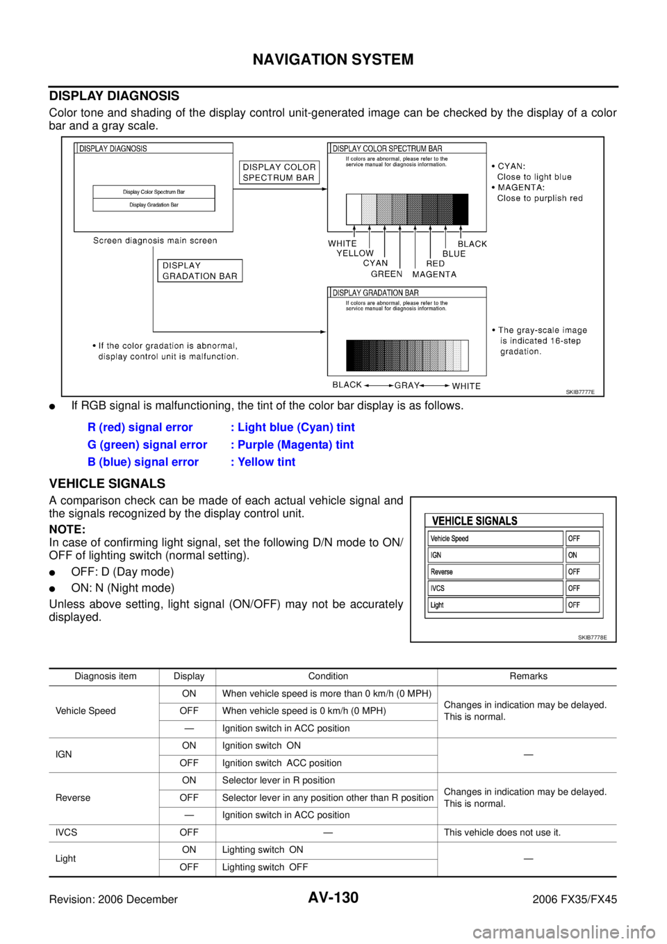
DISPLAY DIAGNOSIS
Color tone and shading of the display control unit-generated image can be checked by the display of a color
bar and a gray scale.
�If RGB signal is malfunctioning, the tint of the color bar display is as follows.
VEHICLE SIGNALS
A comparison check can be made of each actual vehicle signal and
the signals recognized by the display control unit.
NOTE:
In case of confirming light signal, set the following D/N mode to ON/
OFF of lighting switch (normal setting).
�OFF: D (Day mode)
�ON: N (Night mode)
Unless above setting, light signal (ON/OFF) may not be accurately
displayed. R (red) signal error : Light blue (Cyan) tint
G (green) signal error : Purple (Magenta) tint
B (blue) signal error : Yellow tint
SKIB7777E
SKIB7778E
Diagnosis item Display Condition Remarks
Vehicle Speed ON When vehicle speed is more than 0 km/h (0 MPH)
Changes in indication may be delayed.
This is normal.
OFF When vehicle speed is 0 km/h (0 MPH)
— Ignition switch in ACC position
IGN ON Ignition switch ON
—
OFF Ignition switch ACC position
Reverse ON Selector lever in R position
Changes in indication may be delayed.
This is normal.
OFF Selector lever in any position other than R position
— Ignition switch in ACC position
IVCS OFF — This vehicle does not use it.
Light ON Lighting switch ON
—
OFF Lighting switch OFF