Page 3651 of 4462

FRONT FOG LAMP LT-89
C
D E
F
G H
I
J
L
M A
B
LT
Revision: 2006 December 2006 FX35/FX45
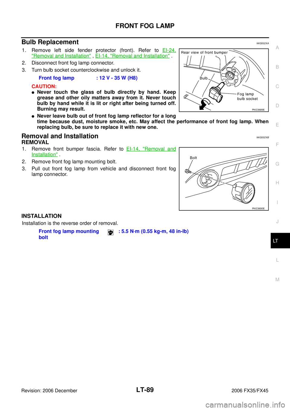
Bulb Replacement NKS002XA
1. Remove left side fender protector (front). Refer to EI-24,
"Removal and Installation" , EI-14, "Removal and Installation" .
2. Disconnect front fog lamp connector.
3. Turn bulb socket counterclockwise and unlock it.
CAUTION:
�Never touch the glass of bulb directly by hand. Keep
grease and other oily matters away from it. Never touch
bulb by hand while it is lit or right after being turned off.
Burning may result.
�Never leave bulb out of front fog lamp reflector for a long
time because dust, moisture smoke, etc. May affect the performance of front fog lamp. When
replacing bulb, be sure to replace it with new one.
Removal and Installation NKS002XB
REMOVAL
1. Remove front bumper fascia. Refer to EI-14, "Removal and
Installation" .
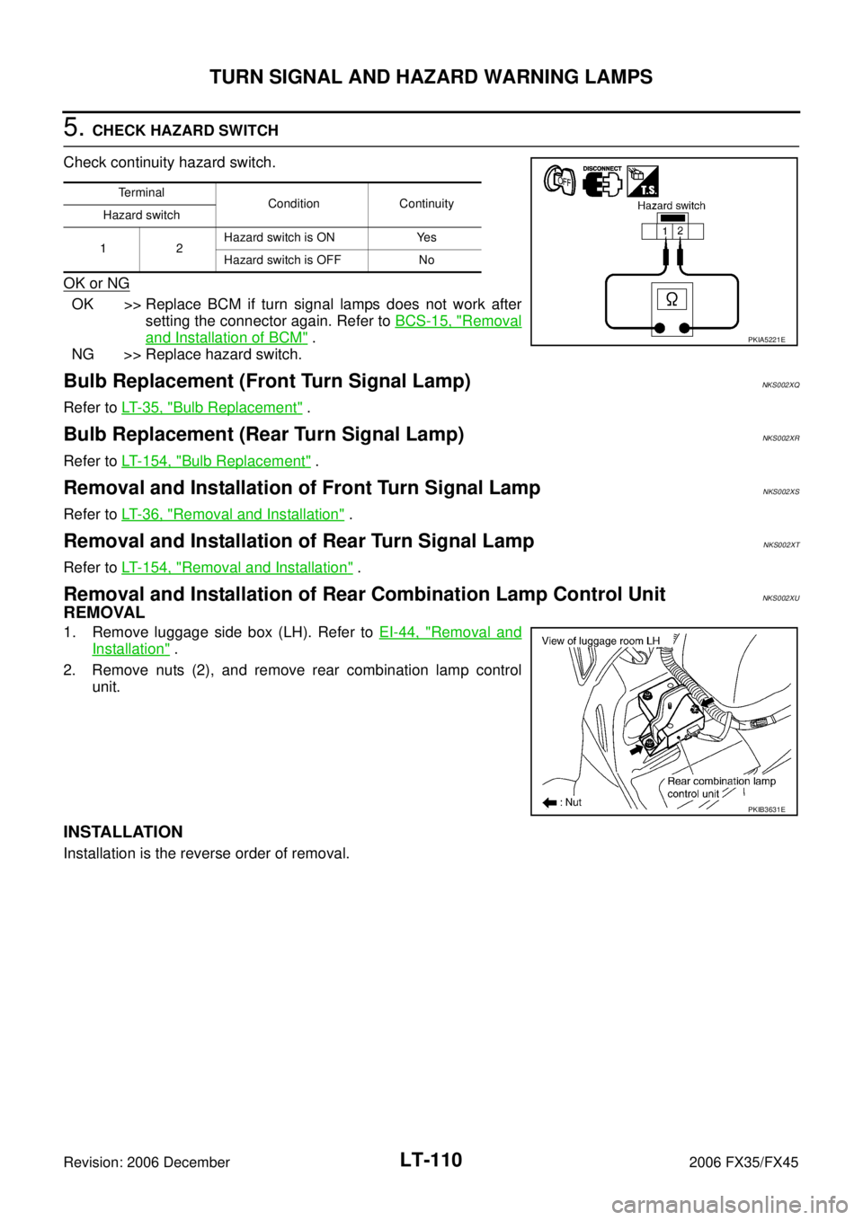
2. Remove front fog lamp mounting bolt.
3. Pull out front fog lamp from vehicle and disconnect front fog lamp connector.
INSTALLATION
Installation is the reverse order of removal. Front fog lamp : 12 V - 35 W (H8)
PKIC9689E
PKIC9690E
Front fog lamp mounting
bolt : 5.5 N·m (0.55 kg-m, 48 in-lb)
Page 3672 of 4462

LT-110
TURN SIGNAL AND HAZARD WARNING LAMPS
Revision: 2006 December 2006 FX35/FX45
5. CHECK HAZARD SWITCH
Check continuity hazard switch.
OK or NG
OK >> Replace BCM if turn signal lamps does not work after setting the connector again. Refer to BCS-15, "
Removal
and Installation of BCM" .
NG >> Replace hazard switch.
Bulb Replacement (Front Turn Signal Lamp)NKS002XQ
Refer to LT- 3 5 , "Bulb Replacement" .
Bulb Replacement (Rear Turn Signal Lamp)NKS002XR
Refer to LT- 1 5 4 , "Bulb Replacement" .
Removal and Installation of Front Turn Signal LampNKS002XS
Refer to LT- 3 6 , "Removal and Installation" .
Removal and Installation of Rear Turn Signal Lamp NKS002XT
Refer to LT- 1 5 4 , "Removal and Installation" .
Removal and Installation of Rear Combination Lamp Control UnitNKS002XU
REMOVAL
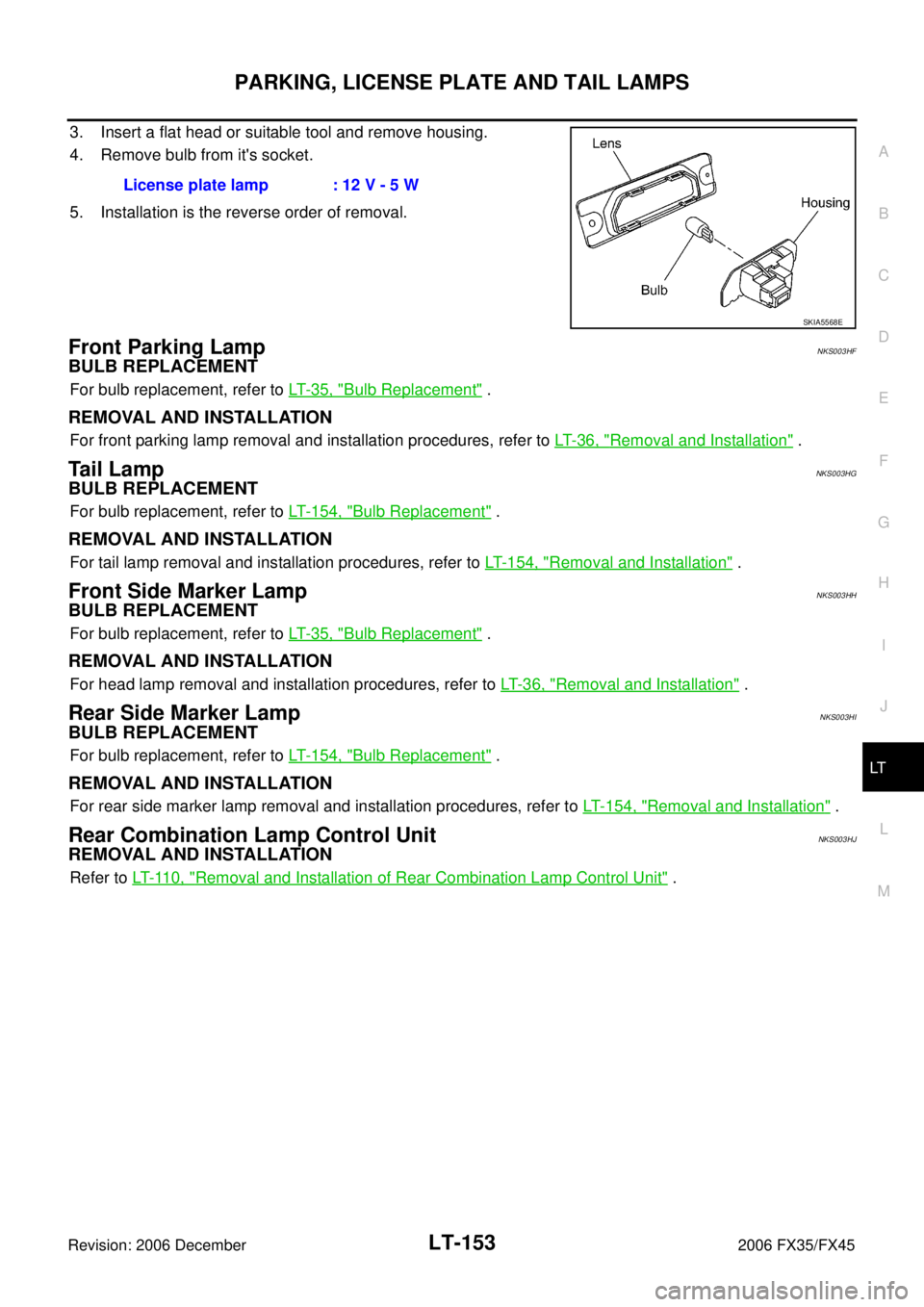
1. Remove luggage side box (LH). Refer to EI-44, "Removal and
Installation" .
2. Remove nuts (2), and remove rear combination lamp control unit.
INSTALLATION
Installation is the reverse order of removal.
Terminal Condition Continuity
Hazard switch
12 Hazard switch is ON Yes
Hazard switch is OFF No
PKIA5221E
PKIB3631E
Page 3712 of 4462
LT-150
PARKING, LICENSE PLATE AND TAIL LAMPS
Revision: 2006 December 2006 FX35/FX45
6. CHECK GROUND
1. Turn ignition switch OFF.
2. Check continuity between front side maker lamp harness con- nector and ground.
3. Check continuity between parking lamp harness connector and ground.
4. Check continuity between license plate lamp harness connector and ground.
5. Check continuity between rear combination lamp harness con- nector and ground.
OK or NG
OK >> Check bulb.
NG >> Repair harness or connector.
Front side marker
lamp connector Terminal
Ground Continuity
RH E22 2Yes
LH E42
PKIA5244E
Parking lamp con-
nector Terminal
Ground Continuity
RH E23 3Yes
LH E43
PKIC9688E
License plate lamp
connector Te r m i n a l
Ground Continuity
RH D111 2Yes
LH D110
PKIA5246E
Rear combination
lamp (Side marker) connector Terminal
Ground Continuity
RH B219 2Yes
LH B57
PKIA5247E
Page 3715 of 4462

PARKING, LICENSE PLATE AND TAIL LAMPS LT-153
C
D E
F
G H
I
J
L
M A
B
LT
Revision: 2006 December 2006 FX35/FX45
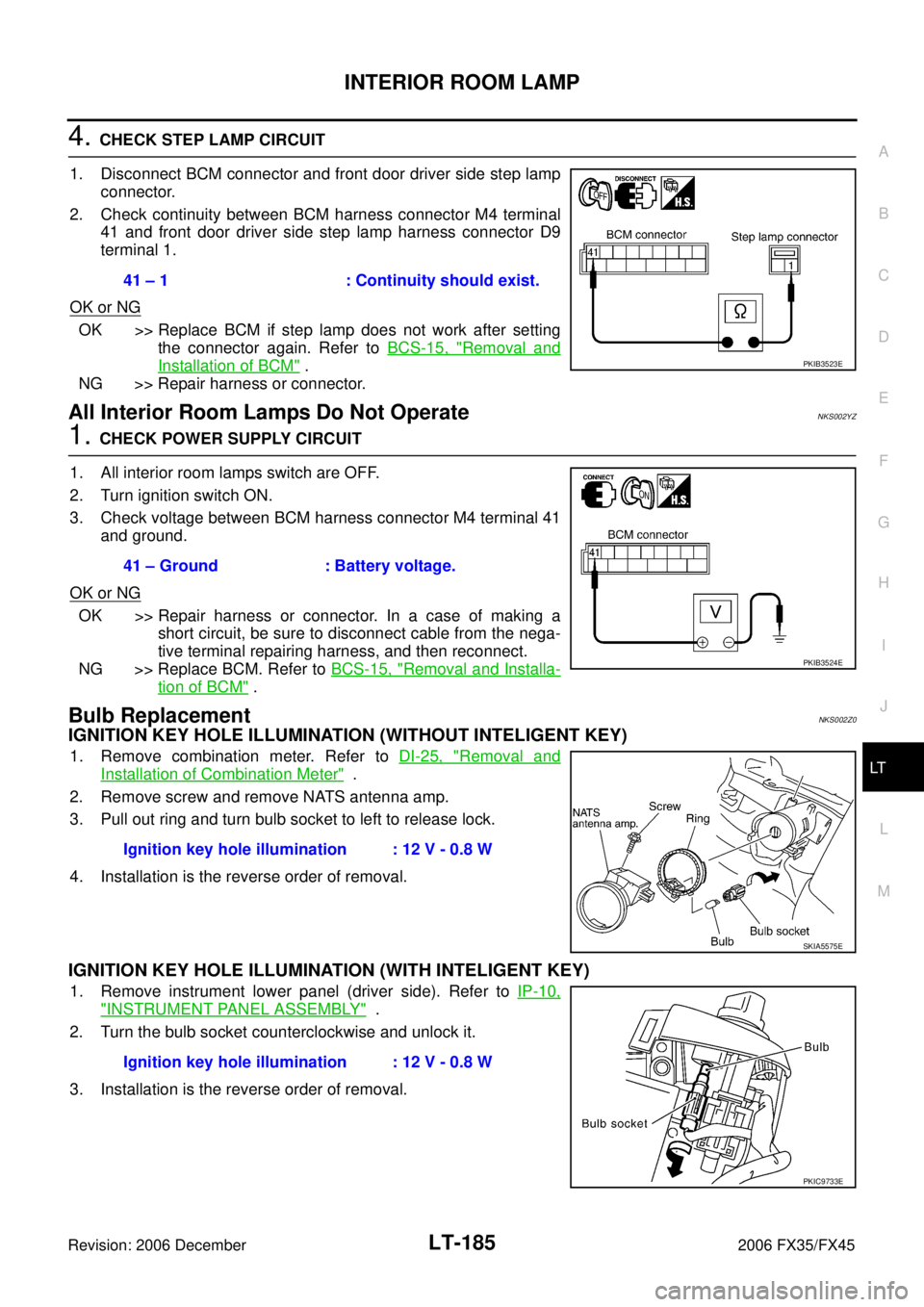
3. Insert a flat head or suitable tool and remove housing.
4. Remove bulb from it's socket.
5. Installation is the reverse order of removal.
Front Parking LampNKS003HF
BULB REPLACEMENT
For bulb replacement, refer to LT- 3 5 , "Bulb Replacement" .
REMOVAL AND INSTALLATION
For front parking lamp removal and installation procedures, refer to LT- 3 6 , "Removal and Installation" .
Ta i l L a m pNKS003HG
BULB REPLACEMENT
For bulb replacement, refer to LT- 1 5 4 , "Bulb Replacement" .
REMOVAL AND INSTALLATION
For tail lamp removal and installation procedures, refer to LT- 1 5 4 , "Removal and Installation" .
Front Side Marker LampNKS003HH
BULB REPLACEMENT
For bulb replacement, refer to LT- 3 5 , "Bulb Replacement" .
REMOVAL AND INSTALLATION
For head lamp removal and installation procedures, refer to LT- 3 6 , "Removal and Installation" .
Rear Side Marker LampNKS003HI
BULB REPLACEMENT
For bulb replacement, refer to LT- 1 5 4 , "Bulb Replacement" .
REMOVAL AND INSTALLATION
For rear side marker lamp removal and installation procedures, refer to LT- 1 5 4 , "Removal and Installation" .
Rear Combination Lamp Control UnitNKS003HJ
REMOVAL AND INSTALLATION
Refer to LT- 11 0 , "Removal and Installation of Rear Combination Lamp Control Unit" .
License plate lamp : 12 V - 5 W
SKIA5568E
Page 3747 of 4462

INTERIOR ROOM LAMP LT-185
C
D E
F
G H
I
J
L
M A
B
LT
Revision: 2006 December 2006 FX35/FX45
4. CHECK STEP LAMP CIRCUIT
1. Disconnect BCM connector and front door driver side step lamp connector.
2. Check continuity between BCM harness connector M4 terminal 41 and front door driver side step lamp harness connector D9
terminal 1.
OK or NG
OK >> Replace BCM if step lamp does not work after setting the connector again. Refer to BCS-15, "
Removal and
Installation of BCM" .
NG >> Repair harness or connector.
All Interior Room Lamps Do Not OperateNKS002YZ
1. CHECK POWER SUPPLY CIRCUIT
1. All interior room lamps switch are OFF.
2. Turn ignition switch ON.
3. Check voltage between BCM harness connector M4 terminal 41 and ground.
OK or NG
OK >> Repair harness or connector. In a case of making a short circuit, be sure to disconnect cable from the nega-
tive terminal repairing harness, and then reconnect.
NG >> Replace BCM. Refer to BCS-15, "
Removal and Installa-
tion of BCM" .
Bulb ReplacementNKS002Z0
IGNITION KEY HOLE ILLUMINATION (WITHOUT INTELIGENT KEY)
1. Remove combination meter. Refer to DI-25, "Removal and
Installation of Combination Meter" .
2. Remove screw and remove NATS antenna amp.
3. Pull out ring and turn bulb socket to left to release lock.
4. Installation is the reverse order of removal.
IGNITION KEY HOLE ILLUMINATION (WITH INTELIGENT KEY)
1. Remove instrument lower panel (driver side). Refer to IP-10,
"INSTRUMENT PANEL ASSEMBLY" .
2. Turn the bulb socket counterclockwise and unlock it.
3. Installation is the reverse order of removal. 41 – 1 : Continuity should exist.
PKIB3523E
41 – Ground : Battery voltage.
PKIB3524E
Ignition key hole illumination : 12 V - 0.8 W
SKIA5575E
Ignition key hole illumination : 12 V - 0.8 W
PKIC9733E
Page 3766 of 4462
LT-204
BULB SPECIFICATIONS
Revision: 2006 December 2006 FX35/FX45
BULB SPECIFICATIONSPFP:26297
HeadlampNKS002Z8
Exterior LampNKS002Z9
Interior Lamp/IlluminationNKS002ZA
Item Wattage (W)
High/Low (Xenon type) 35 (D2S)
Item Wattage (W)
Front combination lamp Front turn signal lamp 21 (amber)
Daytime/Parking lamp 21/5
Front side marker lamp 3.8
Rear combination lamp Stop/Tail lamp and Rear Turn signal lamp LED
Rear side marker lamp 3.8
Front fog lamp 35 (H8)
Back-up lamp 18
License plate lamp 5
High-mounted stop lamp (back door mount) LED
Item Wattage (W)
Map lamp 8
Interior room lamp 10
Personal lamp 8
Luggage room lamp 8
Step lamp 5
Glove box lamp 1.4
Vanity mirror lamp 1.32
Ignition key hole illumination 0.8
A/T device illumination lamp 1.4
Coin box illumination lamp 1.4