Page 942 of 4462

BL-128
INTELLIGENT KEY SYSTEM
Revision: 2006 December 2006 FX35/FX45
3. CHECK IGNITION KNOB SWITCH OPERATION
Check continuity between key switch and ignition knob switch terminals 1 and 2.
OK or NG
OK >> GO TO 4.
NG >> Replace key switch and ignition knob switch.
4. CHECK IGNITION KNOB SWITCH CIRCUIT
1. Disconnect Intelligent Key unit connector.
2. Check continuity between Intelligent Key unit connector M34 terminal 27 (L/W) and key switch and igni- tion knob switch connector M22 terminal 2 (L/W).
3. Check continuity between key switch and ignition knob switch connector terminal 2 (L/W) and ground.
OK or NG
OK >> Replace Intelligent Key unit.
NG >> Repair or replace harness between Intelligent Key unit
and key switch and ignition knob switch.
Connector Terminal Condition Continuity
M22 1 2 Press ignition knob Yes
Return ignition knob
(Release hands from
ignition knob) No
PIIA9929E
27 (L/W) - 2 (L/W) : Continuity should exist.
2 (L/W) - Ground : Continuity should not exist.
PIIA6743E
Page 943 of 4462

INTELLIGENT KEY SYSTEM BL-129
C
D E
F
G H
J
K L
M A
B
BL
Revision: 2006 December 2006 FX35/FX45
Check Door SwitchNIS001NQ
CHECK DOOR SWITCH (EXCEPT BACK DOOR SWITCH)
1. CHECK DOOR SWITCH INPUT SIGNAL
1. Turn ignition knob LOCK position.
2. Check voltage between BCM connector and ground.
OK or NG
OK >> Door switch circuit is OK.
NG >> GO TO 2.
2. CHECK DOOR SWITCH CIRCUIT
1. Disconnect door switch and BCM connector.
2. Check continuity between door switch connector B26, B36, B46, B206 terminals 1 and BCM connector M3, B14 terminals 62, 12, 63, 13.
3. Check continuity between door switch connector B26, B36, B46, B206 terminal 1 and ground.
OK or NG
OK >> GO TO 3.
NG >> Repair or replace harness.
Item Connector Terminals
(Wire color) Door
condition Voltage (V)
(Approx.)
(+) (-)
Driver side B14 62 (W)
Ground CLOSE
↓
OPEN Battery voltage
↓ 0
Rear LH 63 (P)
Passenger side M3 12 (P/B)
Rear RH 13 (P/L)
PIIA7003E
Driver side door
1 (W) –62 (W) : Continuity should exist.
Passenger side door
1 (SB) – 12 (P/B) : Continuity should exist.
Rear door LH
1 (P) – 63 (P) : Continuity should exist.
Rear door RH
1 (P) – 13 (P/L) : Continuity should exist.
1 (W, SB, P) – Ground : Continuity should not exist.
PIIA7004E
Page 944 of 4462

BL-130
INTELLIGENT KEY SYSTEM
Revision: 2006 December 2006 FX35/FX45
3. CHECK DOOR SWITCH
Check continuity between door switch terminal 1 and ground part of door switch.
OK or NG
OK >> Check door switch case ground condition.
NG >> Replace door switch.
CHECK BACK DOOR SWITCH
1. CHECK BACK DOOR SWITCH INPUT SIGNAL
Check voltage between BCM connector and ground.
OK or NG
OK >> Back door switch circuit is OK.
NG >> GO TO 2.
2. CHECK HARNESS CONTINUITY
1. Turn ignition switch OFF.
2. Disconnect BCM and back door closure motor connector.
3. Check continuity between BCM connector B14 terminal 58 and back door closure motor connector D109 terminal 7.
4. Check continuity between BCM connector B14 terminal 58 and ground.
OK or NG
OK >> GO TO 3.
NG >> Repair or replace harness.
Terminal Door switch condition Continuity
1 Ground part of door switch Pushed No
Released Yes
PIIA3351E
Connector Terminals (Wire color)
Condition Voltage (V)
(Approx.)
(+) (–)
B14 58 (L) Ground OPEN 0
CLOSE 9
PIIA6229E
58 (L) – 7 (L) : Continuity should exist.
58 (L) – Ground : Continuity should not exist.
PIIA6226E
Page 945 of 4462

INTELLIGENT KEY SYSTEM BL-131
C
D E
F
G H
J
K L
M A
B
BL
Revision: 2006 December 2006 FX35/FX45
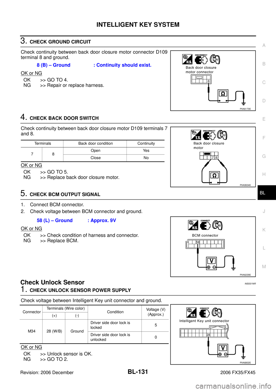
3. CHECK GROUND CIRCUIT
Check continuity between back door closure motor connector D109
terminal 8 and ground.
OK or NG
OK >> GO TO 4.
NG >> Repair or replace harness.
4. CHECK BACK DOOR SWITCH
Check continuity between back door closure motor D109 terminals 7
and 8.
OK or NG
OK >> GO TO 5.
NG >> Replace back door closure motor.
5. CHECK BCM OUTPUT SIGNAL
1. Connect BCM connector.
2. Check voltage between BCM connector and ground.
OK or NG
OK >> Check condition of harness and connector.
NG >> Replace BCM.
Check Unlock SensorNIS001NR
1. CHECK UNLOCK SENSOR POWER SUPPLY
Check voltage between Intelligent Key unit connector and ground.
OK or NG
OK >> Unlock sensor is OK.
NG >> GO TO 2. 8 (B) – Ground : Continuity should exist.
PIIA6170E
Terminals Back door condition Continuity
78 Open Yes
Close No
PIIA9934E
58 (L) – Ground : Approx. 9V
PIIA6229E
Connector Terminals (Wire color)
Condition Voltage (V)
(Approx.)
(+) (-)
M34 28 (W/B) Ground Driver side door lock is
locked 5
Driver side door lock is
unlocked 0
PIIA6802E
Page 949 of 4462

INTELLIGENT KEY SYSTEM BL-135
C
D E
F
G H
J
K L
M A
B
BL
Revision: 2006 December 2006 FX35/FX45
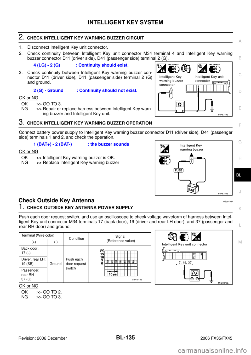
2. CHECK INTELLIGENT KEY WARNING BUZZER CIRCUIT
1. Disconnect Intelligent Key unit connector.
2. Check continuity between Intelligent Key unit connector M34 terminal 4 and Intelligent Key warning buzzer connector D11 (driver side), D41 (passenger side) terminal 2 (G).
3. Check continuity between Intelligent Key warning buzzer con- nector D11 (driver side), D41 (passenger side) terminal 2 (G)
and ground.
OK or NG
OK >> GO TO 3.
NG >> Repair or replace harness between Intelligent Key warn-
ing buzzer and Intelligent Key unit.
3. CHECK INTELLIGENT KEY WARNING BUZZER OPERATION
Connect battery power supply to Intelligent Key warning buzzer connector D11 (driver side), D41 (passenger
side) terminals 1 and 2, and check the operation.
OK or NG
OK >> Intelligent Key warning buzzer is OK.
NG >> Replace Intelligent Key warning buzzer
Check Outside Key AntennaNIS001NU
1. CHECK OUTSIDE KEY ANTENNA POWER SUPPLY
Push each door request switch, and use an oscilloscope to check voltage waveform of harness between Intel-
ligent Key unit connector M34 terminals 17 (back door), 19 (driver and rear LH door), and 37 (passenger and
rear RH door) and ground.
OK or NG
OK >> GO TO 2.
NG >> GO TO 3. 4 (LG) - 2 (G) : Continuity should exist.
2 (G) - Ground : Continuity should not exist.
PIIA6749E
1 (BAT+) - 2 (BAT-) : the buzzer sounds
PIIA6750E
Terminal (Wire color) Condition Signal
(Reference value)
(+) (-)
Back door:
17 (L)
Ground Push each
door request
switch
Driver, rear LH:
19 (SB)
Passenger,
rear RH
37 (G)
MIIB0375ESIIA1910J
Page 956 of 4462
BL-142
INTELLIGENT KEY SYSTEM
Revision: 2006 December 2006 FX35/FX45
3. CHECK STOP LAMP SWITCH GROUND CIRCUIT
1. Check continuity between stop lamp switch connector E210 ter- minal 2 (P) and Intelligent Key unit connector M34 terminal 26
(P/L).
2. Check continuity between stop lamp switch connector E210 ter- minal 2 (P) and ground.
OK or NG
OK >> Stop lamp switch is OK.
NG >> Repair or replace harness.
Check Detention SwitchNIS001NY
1. CHECK DETENTION SWITCH INPUT SIGNAL
1. Turn ignition knob LOCK position.
2. Check voltage between Intelligent Key unit connector and ground.
OK or NG
OK >> Door switch circuit is OK.
NG >> GO TO 2. 2 (P) - 26 (P/L) : Continuity should exist.
2 (P) - Ground : Continuity should not exist.
PIIA6801E
Connector Terminal
(Wire color) Condition Voltage (V)
(Approx.)
(+) (-)
M34 39 (R/Y) Ground When selector lever is locked
at the “P” position 0
When selector lever is not
locked at the “P” position Battery voltage
PIIA6805E
Page 957 of 4462
INTELLIGENT KEY SYSTEM BL-143
C
D E
F
G H
J
K L
M A
B
BL
Revision: 2006 December 2006 FX35/FX45
2. CHECK DETENTION SWITCH CIRCUIT
1. Disconnect A/T device (detention switch) connector.
2. Check voltage between A/T device (detention switch) connector M67 terminal 3 (R/Y) and ground. (Check harness for open.)
3. Check continuity between A/T device (detention switch) connec- tor M67 terminals 3 (R/Y) and ground. (Check harness for
short.)
OK or NG
OK >> GO TO 3.
NG >> Repair or replace harness.
3. CHECK DETENTION SWITCH
Check continuity between A/T device (detention switch) terminals 2 and 3.
OK or NG
OK >> GO TO 4.
NG >> Replace back A/T device (detention switch). 3 (R/Y) – Ground : Battery voltage
PIIA6806E
3 (R/Y) – Ground : Continuity should not exist.
PIIA6807E
Terminal Condition Continuity
23 When selector lever is not
locked at the “P” position No
When selector lever is
locked at the “P” position Ye s
PIIA6808E
Page 984 of 4462

BL-170
BACK DOOR AUTO CLOSURE SYSTEM
Revision: 2006 December 2006 FX35/FX45
Check Back Door Closure Control Unit Power Supply and Ground CircuitNIS001OT
1. CHECK POWER SUPPLY CIRCUIT
1. Turn ignition switch OFF.
2. Check voltage between back door closure control unit connector D106 terminal 1 and ground.
OK or NG
OK >> GO TO 2.
NG >> Check the following.
�15A fuse [No.18, located in fuse block (J/B)]
�Harness for open or short between back door closure
control unit and fuse.
2. CHECK GROUND CIRCUIT
1. Disconnect back door closure control unit connector.
2. Check continuity between back door closure control unit con- nector D106 terminal 4 and ground.
OK or NG
OK >> Power supply and ground circuit are OK.
NG >> Repair or replace harness.
Check Half-Latch SwitchNIS001OU
1. CHECK HALF-LATCH SWITCH SIGNAL
1. Turn ignition switch OFF.
2. Check the signal between back door closure control unit connector and ground with oscilloscope.
OK or NG
OK >> Half-latch switch is OK.
NG >> GO TO 2. 1 (R) – Ground : Battery voltage
PIIA6166E
4 (B) – Ground : Continuity should exist.
PIIA6167E
Con-
nector Terminals (Wire color)
Back door
condition Signal
(Reference value)
(+) (-)
D106 7 (OR) Ground Fully open
→
fully closed
PIIA6168E
SIIA1479J