Page 4110 of 4462

SC-4
BATTERY
Revision: 2006 December 2006 FX35/FX45
BATTERYPFP:AYBGL
How to Handle BatteryNKS0056P
CAUTION:
�If it becomes necessary to start the engine with a booster battery and jumper cables, use a 12-volt
booster battery.
�After connecting battery cables, ensure that they are tightly clamped to battery terminals for good
contact.
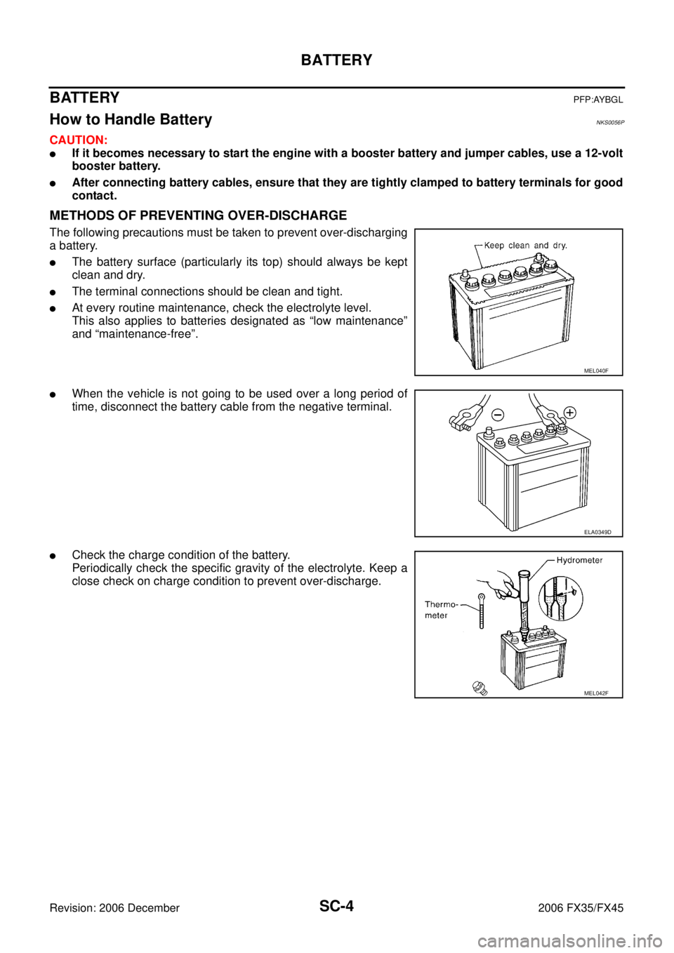
METHODS OF PREVENTING OVER-DISCHARGE
The following precautions must be taken to prevent over-discharging
a battery.
�The battery surface (particularly its top) should always be kept
clean and dry.
�The terminal connections should be clean and tight.
�At every routine maintenance, check the electrolyte level.
This also applies to batteries designated as “low maintenance”
and “maintenance-free”.
�When the vehicle is not going to be used over a long period of
time, disconnect the battery cable from the negative terminal.
�Check the charge condition of the battery.
Periodically check the specific gravity of the electrolyte. Keep a
close check on charge condition to prevent over-discharge.
MEL040F
ELA0349D
MEL042F
Page 4114 of 4462

SC-8
STARTING SYSTEM
Revision: 2006 December 2006 FX35/FX45
STARTING SYSTEMPFP:23300
System Description NKS002UQ
Power is supplied at all times
�through 40A fusible link (letter F, located in the fuse and fusible link block)
�to ignition switch terminal 1,
�through 15A fuse (No. 78, located in the IPDM E/R)
�to CPU of IPDM E/R,
�through 10A fuse (No. 71, located in the IPDM E/R)
�to CPU of IPDM E/R.
When the selector lever in the P or N position, power is supplied
�from TCM, and through A/T assembly terminal 9
�to IPDM E/R terminal 53.
Ground is supplied
�to IPDM E/R terminals 38, 50 and 60
�from grounds E21, E50 and E51.
With the ignition switch in the START position, and provided that the IPDM E/R receives a starter relay ON sig-
nal from the CAN lines, the IPDM E/R is energized and power is supplied
�from ignition switch terminal 5
�to IPDM E/R terminal 4 and
�through IPDM E/R terminal 3
�to starter motor terminal 1.
The starter motor plunger closes and provides a closed circuit between the battery and starter motor. The
starter motor is grounded to the engine block. With power and ground supplied, cranking occurs and the
engine starts.
Page 4115 of 4462
STARTING SYSTEM SC-9
C
D E
F
G H
I
J
L
M A
B
SC
Revision: 2006 December 2006 FX35/FX45
Wiring Diagram — START —NKS002UR
VK45DE ENGINE MODELS
TKWM1275E
Page 4116 of 4462
SC-10
STARTING SYSTEM
Revision: 2006 December 2006 FX35/FX45
VQ35DE ENGINE MODELS
TKWM1276E
Page 4118 of 4462

SC-12
STARTING SYSTEM
Revision: 2006 December 2006 FX35/FX45
DIAGNOSTIC PROCEDURE 1
Check “B” Terminal Circuit
1. CHECK POWER SUPPLY FOR STARTER MOTOR “B” TERMINAL
1. Remove fuel pump fuse.
2. Crank or start the engine (where possible) until the fuel pressure is released.
3. Turn ignition switch OFF.
4. Make sure that the starter motor “B” terminal E313 terminal 2 connection is clean and tight.
5. Check voltage between starter motor “B” terminal E313 terminal 2 and ground.
OK or NG
OK >> GO TO 2.
NG >> Check harness between battery and starter motor for open circuit.
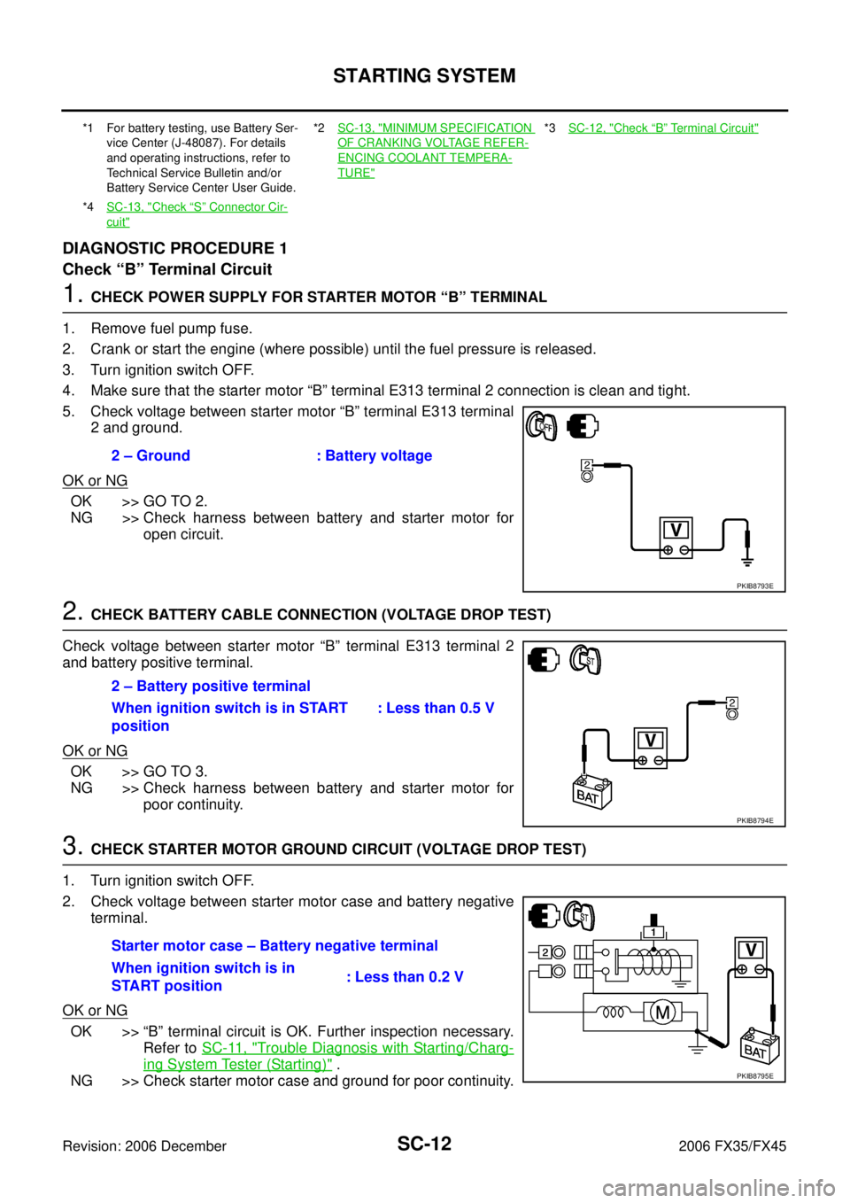
2. CHECK BATTERY CABLE CONNECTION (VOLTAGE DROP TEST)
Check voltage between starter motor “B” terminal E313 terminal 2
and battery positive terminal.
OK or NG
OK >> GO TO 3.
NG >> Check harness between battery and starter motor for poor continuity.
3. CHECK STARTER MOTOR GROUND CIRCUIT (VOLTAGE DROP TEST)
1. Turn ignition switch OFF.
2. Check voltage between starter motor case and battery negative terminal.
OK or NG
OK >> “B” terminal circuit is OK. Further inspection necessary. Refer to SC-11, "
Trouble Diagnosis with Starting/Charg-
ing System Tester (Starting)" .
NG >> Check starter motor case and ground for poor continuity.
*1 For battery testing, use Battery Ser-
vice Center (J-48087). For details
and operating instructions, refer to
Technical Service Bulletin and/or
Battery Service Center User Guide. *2
SC-13, "MINIMUM SPECIFICATION
OF CRANKING VOLTAGE REFER-
ENCING COOLANT TEMPERA-
TURE"
*3SC-12, "Check “B” Terminal Circuit"
*4SC-13, "Check “S” Connector Cir-
cuit"
2 – Ground : Battery voltage
PKIB8793E
2 – Battery positive terminal
When ignition switch is in START
position : Less than 0.5 V
PKIB8794E
Starter motor case – Battery negative terminal
When ignition switch is in
START position : Less than 0.2 V
PKIB8795E
Page 4119 of 4462

STARTING SYSTEM SC-13
C
D E
F
G H
I
J
L
M A
B
SC
Revision: 2006 December 2006 FX35/FX45
DIAGNOSTIC PROCEDURE 2
Check “S” Connector Circuit
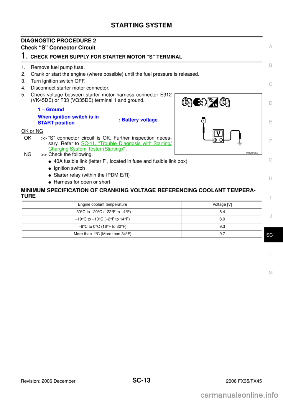
1. CHECK POWER SUPPLY FOR STARTER MOTOR “S” TERMINAL
1. Remove fuel pump fuse.
2. Crank or start the engine (where possible) until the fuel pressure is released.
3. Turn ignition switch OFF.
4. Disconnect starter motor connector.
5. Check voltage between starter motor harness connector E312 (VK45DE) or F33 (VQ35DE) terminal 1 and ground.
OK or NG
OK >> “S” connector circuit is OK. Further inspection neces- sary. Refer to SC-11, "
Trouble Diagnosis with Starting/
Charging System Tester (Starting)" .
NG >> Check the following.
�40A fusible link (letter F , located in fuse and fusible link box)
�Ignition switch
�Starter relay (within the IPDM E/R)
�Harness for open or short
MINIMUM SPECIFICATION OF CRANKING VOLTAGE REFERENCING COOLANT TEMPERA-
TURE
1 – Ground
When ignition switch is in
START position : Battery voltage
PKIB8796E
Engine coolant temperature Voltage [V]
− 30 °C to −20 °C ( −22 °F to −4°F) 8.4
− 19 °C to −10 °C ( −2°F to 14 °F) 8.9
− 9°C to 0 °C (16 °F to 32 °F) 9.3
More than 1 °C (More than 34 °F) 9.7
Page 4120 of 4462
SC-14
STARTING SYSTEM
Revision: 2006 December 2006 FX35/FX45
Removal and Installation NKS002UT
VK45DE ENGINE MODELS
Removal
1. Disconnect the battery cable from the negative terminal.
2. Remove engine front and rear undercover, using power tools.
3. Disconnect “S” connector.
4. Remove “B” terminal nut.
5. Remove starter motor mounting bolts.
6. Loosen A/T fluid cooler tube clip bolts. Refer to AT- 2 6 6 ,
"TRANSMISSION ASSEMBLY" .
7. Remove starter motor downward from the vehicle.
Installation
Installation is the reverse order of removal.
CAUTION:
Be sure to tighten “B” terminal nut carefully.
1. Starter motor 2. Starter motor mounting bolt 3. B terminal harness
4. B terminal nut 5. S connector 6. Cylinder block
: N·m (kg-m, ft-lb) : Engine front
SKIB7206E
PKIA2810E
Page 4121 of 4462
STARTING SYSTEM SC-15
C
D E
F
G H
I
J
L
M A
B
SC
Revision: 2006 December 2006 FX35/FX45
VQ35DE ENGINE MODELS (2WD)
Removal
1. Disconnect the battery cable from the negative terminal.
2. Remove engine rear undercover, using power tools.
3. Disconnect “S” connector.
4. Remove “B” terminal nut.
5. Remove starter motor mounting bolts and harness clip bracket, using power tools.
6. Remove starter motor downward from the vehicle.
Installation
Installation is the reverse order of removal.
CAUTION:
Be sure to tighten “B” terminal nut carefully.
1. Starter motor mounting bolt 2. Harness clip bracket 3. S connector
4. B terminal nut 5. B terminal harness 6. Starter motor
7. Oil pan : N·m (kg-m, ft-lb) : N·m (kg-m, in-lb) : Engine front
PKIB8799E
PKIA2812E