Page 647 of 4462

AUDIO AV-41
C
D E
F
G H
I
J
L
M A
B
AV
Revision: 2006 December 2006 FX35/FX45
2. CHECK AMP. ON SIGNAL
1. Connect audio unit connector.
2. Turn ignition switch ACC.
3. Check voltage between audio unit harness connector M59 ter- minal 12 and ground.
OK or NG
OK >> INSPECTION END (System is OK.)
NG >> Replace audio unit.
Vehicle Speed Signal InspectionNKS003B0
1. CHECK VEHICLE SPEED OPERATION
Start engine and drive vehicle.
Dose speedometer is operated normally?
YES >> GO TO 2.
NO >> Check combination meter trouble diagnosis. Refer to DI-16, "
Trouble Diagnosis" .
2. CHECK HARNESS
1. Turn ignition switch OFF.
2. Disconnect audio unit and unified meter and A/C amp. connectors.
3. Check continuity between audio unit harness connector M60 ter- minal 22 and unified meter and A/C amp. harness connector
M56 terminal 34.
4. Check continuity between audio unit harness connector M60 ter- minal 22 and ground.
OK or NG
OK >> GO TO 3.
NG >> Repair harness or connector. 12 – Ground : Approx. 12 V
SKIA6818E
22 – 34 : Continuity should exist.
22 – Ground : Continuity should not exist.
SKIA6807E
Page 648 of 4462

AV-42
AUDIO
Revision: 2006 December 2006 FX35/FX45
3. CHECK VEHICLE SPEED SIGNAL
1. Connect audio unit and unified meter and A/C amp. connectors.
2. Start engine and drive vehicle at more than 40 km/h (25 MPH).
3. Check the signal between audio unit harness connector M60 terminal 22 and ground with CONSULT-II or oscilloscope.
OK or NG
OK >> INSPECTION END (System is OK.)
NG >> Replace unified meter and A/C amp.
Locking CD Auto-Changer MechanismNKS003B1
CAUTION:
�Prior to removing a malfunctioning CD auto-changer unit that will be shipped for repair, the
changer mechanism MUST BE LOCKED to prevent the mechanism from being damaged during
shipping.
�If a CD is jammed or unable to be removed from the unit, do NOT lock the changer mechanism. If
the unit is to be shipped for repair, carefully package the unit to prevent vibration and shock.
DAMPER LOCK PROCEDURE
1. Eject and remove any CDs from the audio unit.
2. Turn ignition switch OFF. Wait until audio unit display is off and mechanism stops moving (mechanism sound stops).
3. Press any one of the disc selection buttons once. When a display shows on the audio unit, press the same disc selection button again within 5 seconds.
�The changer mechanism will lock itself within 10 seconds.
4. After mechanism stops moving (mechanism sound stops), open the driver and passenger window, and then disconnect negative battery cable.
NOTE:
After installing a new or remanufactured audio unit, switching the audio unit ON will automatically unlock the
mechanism. A special unlocking procedure is not required.
Terminal Condition Reference
signal
(+) (–)
22 Ground When vehicle speed is
approx. 40 km/h (25 MPH)
SKIA6809E
ELF1080D
Page 654 of 4462
AV-48
ANTENNA
Revision: 2006 December 2006 FX35/FX45
ANTENNAPFP:28200
System DescriptionNKS003LP
With the ignition switch in ACC or ON, power is supplied
�through 10A fuse [No. 6, located in the fuse block (J/B)]
�to audio unit terminal 10.
Ground is supplied through the case of the antenna amp.
When the radio switch is turned ON, antenna signal is supplied
�through audio unit terminal 5
�to the antenna amp.
Then the antenna amp. is activated.
The amplified radio signals are supplied to the audio unit through the antenna amp.
Page 656 of 4462
AV-50
ANTENNA
Revision: 2006 December 2006 FX35/FX45
Terminals and Reference Value for Audio UnitNKS003LR
Antenna Amp. InspectionNKS003LS
1. CHECK ANTENNA FEEDER
Check with visual observation if antenna feeder between audio unit and antenna amp. has disconnection or
malfunction on the mounting part (engagement, looseness of shield earth, etc.).
OK or NG
OK >> GO TO 2
NG >> Replace antenna feeder.
2. CHECK ANTENNA SIGNAL
1. Turn ignition switch ACC.
2. Check voltage between audio unit harness connector M58 ter- minal 5 and ground.
OK or NG
OK >> INSPECTION END (System is OK.)
NG >> Replace audio unit.
Terminal
(Wire color) Item Signal
input/
output Condition
Reference value
+– Ignition
switch Operation
5 (R/W) Ground Antenna signal Input ACC — Approx. 12 V
10 (LG) Ground ACC power
supply Input ACC — Battery voltage
5 – Ground : Approx. 12 V
SKIA6854E
Page 693 of 4462

INTEGRATED DISPLAY SYSTEM AV-87
C
D E
F
G H
I
J
L
M A
B
AV
Revision: 2006 December 2006 FX35/FX45
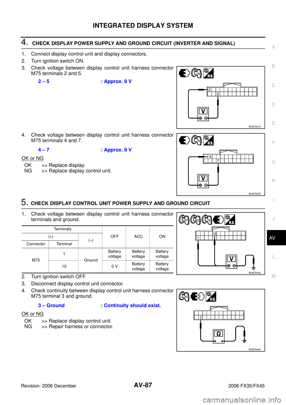
4. CHECK DISPLAY POWER SUPPLY AND GROUND CIRCUIT (INVERTER AND SIGNAL)
1. Connect display control unit and display connectors.
2. Turn ignition switch ON.
3. Check voltage between display control unit harness connector M75 terminals 2 and 5.
4. Check voltage between display control unit harness connector M75 terminals 4 and 7.
OK or NG
OK >> Replace display.
NG >> Replace display control unit.
5. CHECK DISPLAY CONTROL UNIT POWER SUPPLY AND GROUND CIRCUIT
1. Check voltage between display control unit harness connector terminals and ground.
2. Turn ignition switch OFF.
3. Disconnect display control unit connector.
4. Check continuity between display control unit harness connector M75 terminal 3 and ground.
OK or NG
OK >> Replace display control unit.
NG >> Repair harness or connector. 2 – 5 : Approx. 9 V
SKIB7841E
4 – 7 : Approx. 9 V
SKIB7842E
Te r m i n a l s
OFF ACC ON
(+)
(–)
Connector Terminal
M75 1
Ground Battery
voltage Battery
voltage Battery
voltage
10 0 V Battery
voltage Battery
voltage
3 – Ground : Continuity should exist.
SKIB7843E
SKIB7844E
Page 695 of 4462

INTEGRATED DISPLAY SYSTEM AV-89
C
D E
F
G H
I
J
L
M A
B
AV
Revision: 2006 December 2006 FX35/FX45
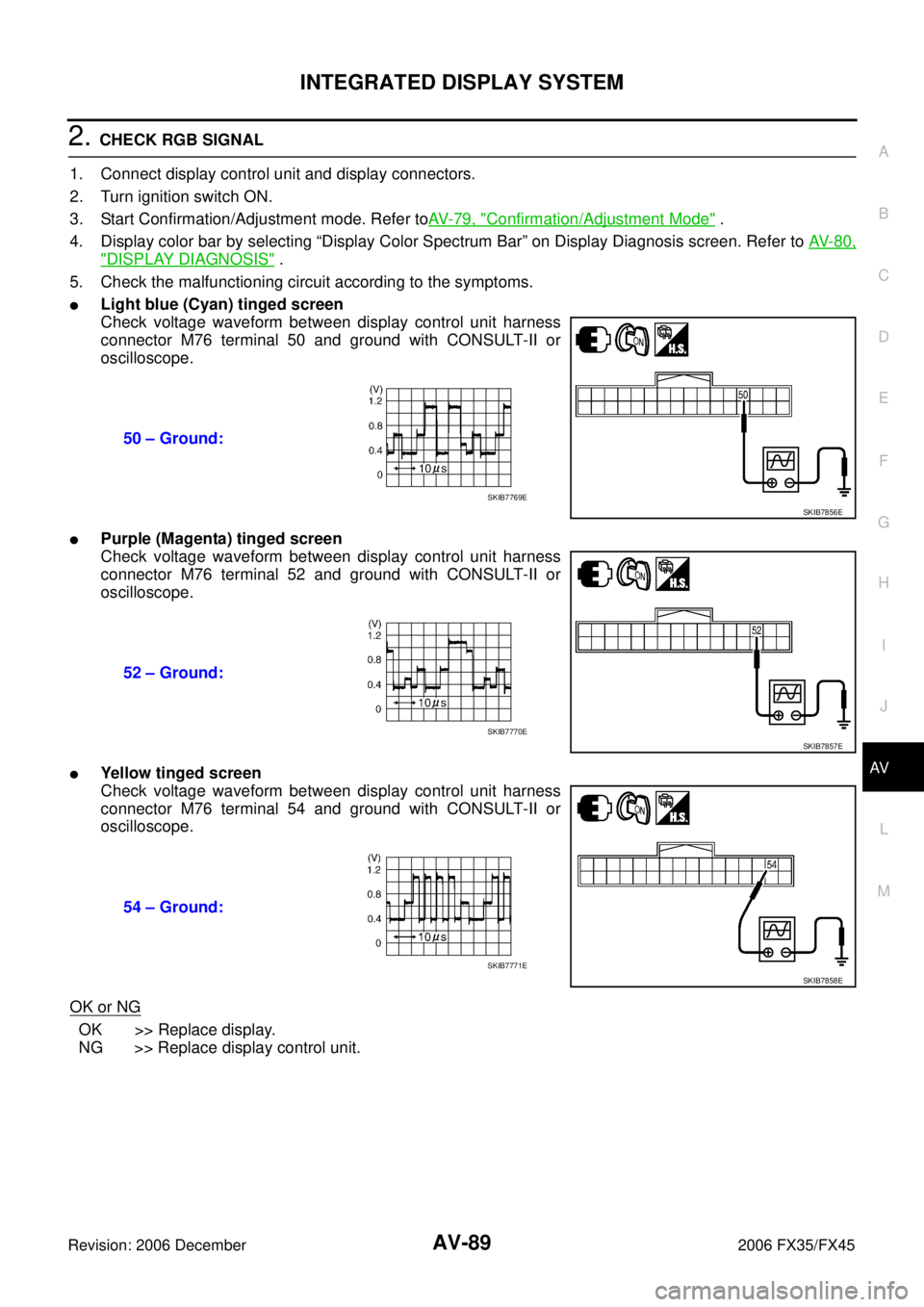
2. CHECK RGB SIGNAL
1. Connect display control unit and display connectors.
2. Turn ignition switch ON.
3. Start Confirmation/Adjustment mode. Refer to AV- 7 9 , "
Confirmation/Adjustment Mode" .
4. Display color bar by selecting “Display Color Spectrum Bar” on Display Diagnosis screen. Refer to AV- 8 0 ,
"DISPLAY DIAGNOSIS" .
5. Check the malfunctioning circuit according to the symptoms.
�Light blue (Cyan) tinged screen
Check voltage waveform between display control unit harness
connector M76 terminal 50 and ground with CONSULT-II or
oscilloscope.
�Purple (Magenta) tinged screen
Check voltage waveform between display control unit harness
connector M76 terminal 52 and ground with CONSULT-II or
oscilloscope.
�Yellow tinged screen
Check voltage waveform between display control unit harness
connector M76 terminal 54 and ground with CONSULT-II or
oscilloscope.
OK or NG
OK >> Replace display.
NG >> Replace display control unit. 50 – Ground:
SKIB7856ESKIB7769E
52 – Ground:
SKIB7857ESKIB7770E
54 – Ground:
SKIB7858ESKIB7771E
Page 696 of 4462

AV-90
INTEGRATED DISPLAY SYSTEM
Revision: 2006 December 2006 FX35/FX45
RGB Image Is RollingNKS003JP
Symptom: RGB image is rolling.
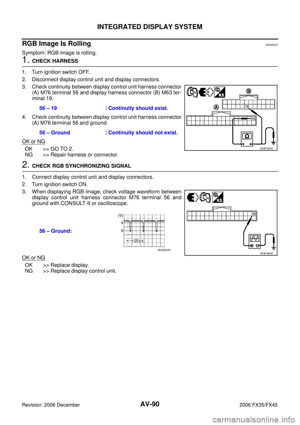
1. CHECK HARNESS
1. Turn ignition switch OFF.
2. Disconnect display control unit and display connectors.
3. Check continuity between display control unit harness connector (A) M76 terminal 56 and display harness connector (B) M63 ter-
minal 19.
4. Check continuity between display control unit harness connector (A) M76 terminal 56 and ground.
OK or NG
OK >> GO TO 2.
NG >> Repair harness or connector.
2. CHECK RGB SYNCHRONIZING SIGNAL
1. Connect display control unit and display connectors.
2. Turn ignition switch ON.
3. When displaying RGB image, check voltage waveform between display control unit harness connector M76 terminal 56 and
ground with CONSULT-II or oscilloscope.
OK or NG
OK >> Replace display.
NG >> Replace display control unit. 56 – 19 : Continuity should exist.
56 – Ground : Continuity should not exist.
SKIB7863E
56 – Ground:
SKIB7864ESKIB3603E
Page 700 of 4462

AV-94
NAVIGATION SYSTEM
Revision: 2006 December 2006 FX35/FX45
NAVIGATION SYSTEM
Location Detection Principle
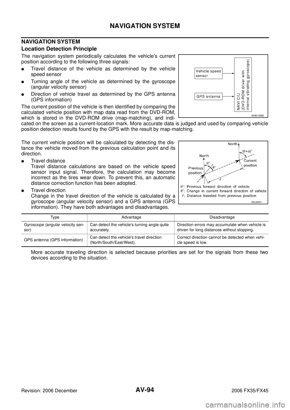
The navigation system periodically calculates the vehicle's current
position according to the following three signals:
�Travel distance of the vehicle as determined by the vehicle
speed sensor
�Turning angle of the vehicle as determined by the gyroscope
(angular velocity sensor)
�Direction of vehicle travel as determined by the GPS antenna
(GPS information)
The current position of the vehicle is then identified by comparing the
calculated vehicle position with map data read from the DVD-ROM,
which is stored in the DVD-ROM drive (map-matching), and indi-
cated on the screen as a current-location mark. More accurate data is judged and used by comparing vehicle
position detection results found by the GPS with the result by map-matching.
The current vehicle position will be calculated by detecting the dis-
tance the vehicle moved from the previous calculation point and its
direction.
�Travel distance
Travel distance calculations are based on the vehicle speed
sensor input signal. Therefore, the calculation may become
incorrect as the tires wear down. To prevent this, an automatic
distance correction function has been adopted.
�Travel direction
Change in the travel direction of the vehicle is calculated by a
gyroscope (angular velocity sensor) and a GPS antenna (GPS
information). They have both advantages and disadvantages.
More accurate traveling direction is selected because priorities are set for the signals from these two
devices according to the situation.
SKIB1058E
SEL684V
Type Advantage Disadvantage
Gyroscope (angular velocity sen-
sor) Can detect the vehicle's turning angle quite
accurately. Direction errors may accumulate when vehicle is
driven for long distances without stopping.
GPS antenna (GPS information) Can detect the vehicle's travel direction
(North/South/East/West). Correct direction cannot be detected when vehi-
cle speed is low.