Page 67 of 289
1
FEATURES OF YOUR HYUNDAI
55
Reset
Switch
B310B02JMHJM2185
A Type
B Type2. Trip odometerThis mode indicates the drive distance travelled
since the last reset.
TRIP COMPUTERB400B02JM-AAT(If installed)The trip computer is a microcomputer-con-
trolled driver information gauge that displays
information related to driving, such as a tripmeter,
average fuel consumption and distance to empty
on the LCD.
HJM2185
TRIPMETER
DISTANCE TO EMPTY
AVERAGE FUEL CONSUMPTION
Trip Computer Switcho The trip computer switch is used to zero the
multi-functional display mode.
o Pushing in the trip computer switch behind
the right side of the steering wheel changes
the display as follows;
Page 72 of 289
1FEATURES OF YOUR HYUNDAI60
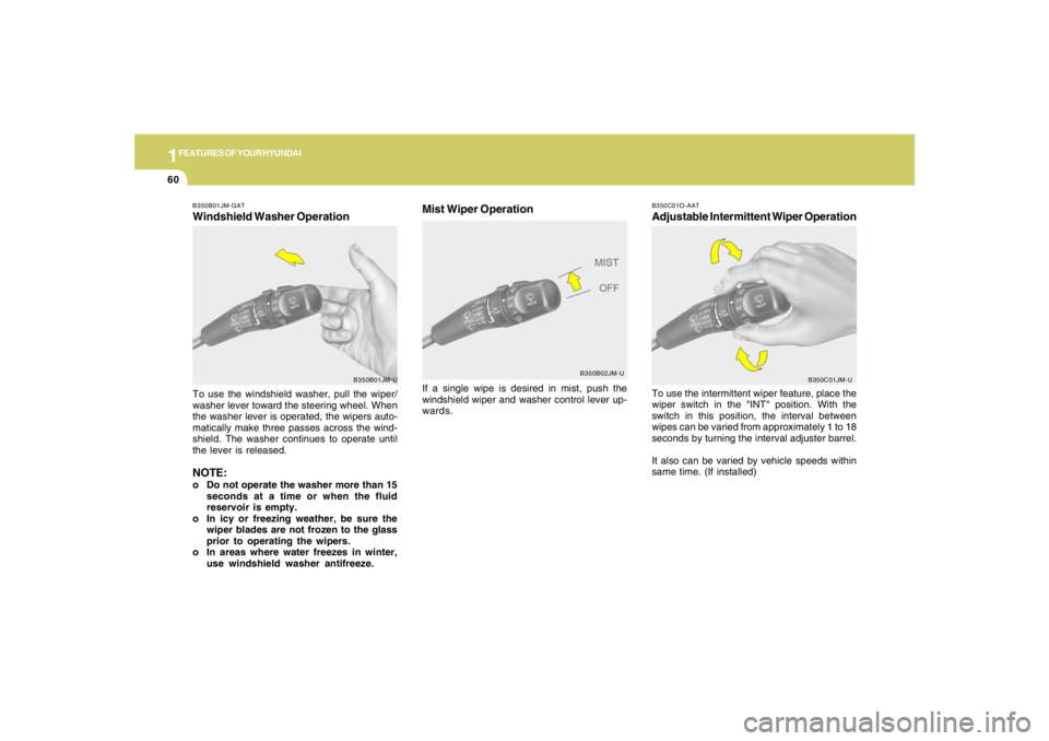
B350C01O-AATAdjustable Intermittent Wiper OperationTo use the intermittent wiper feature, place the
wiper switch in the "INT" position. With the
switch in this position, the interval between
wipes can be varied from approximately 1 to 18
seconds by turning the interval adjuster barrel.
It also can be varied by vehicle speeds within
same time. (If installed)
B350C01JM-U
If a single wipe is desired in mist, push the
windshield wiper and washer control lever up-
wards.
B350B01JM-GATWindshield Washer OperationTo use the windshield washer, pull the wiper/
washer lever toward the steering wheel. When
the washer lever is operated, the wipers auto-
matically make three passes across the wind-
shield. The washer continues to operate until
the lever is released.NOTE:o Do not operate the washer more than 15
seconds at a time or when the fluid
reservoir is empty.
o In icy or freezing weather, be sure the
wiper blades are not frozen to the glass
prior to operating the wipers.
o In areas where water freezes in winter,
use windshield washer antifreeze.
B350B01JM-U
Mist Wiper Operation
B350B02JM-U
Page 86 of 289
1FEATURES OF YOUR HYUNDAI74
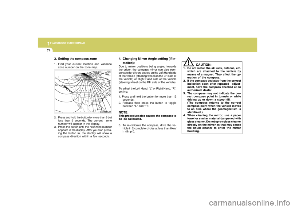
3. Setting the compass zone1. Find your current location and variance
zone number on the zone map.
CAUTION:
1. Do not install the ski rack, antenna, etc.
which are attached to the vehicle by
means of a magnet. They affect the op-
eration of the compass.
2. If the compass deviates from the correct
indication soon after repeated adjust-
ment, have the compass checked at an
authorized dealer.
3. The compass may not indicate the cor-
rect compass point in tunnels or while
driving up or down a steep hill.
(The compass returns to the correct
compass point when the vehicle moves
to an area where the geomagnetism is
stabilized.)
4. When cleaning the mirror, use a paper
towel or similar material dampened with
glass cleaner. Do not spray glass cleaner
directly on the mirror as that may cause
the liquid cleaner to enter the mirror
housing.
!
2. Press and hold the button for more than 6 but
less than 9 seconds. The current zone
number will appear in the display.
3. Press the button until the new zone number
appears in the display. After you stop press-
ing the button in, the display will show a
compass direction within a few seconds.
B520C06JM
4. Changing Mirror Angle setting (If In-
stalled):Due to mirror positions being angled towards
the driver, the compass mirror can also com-
pensate for drivers seated on the Left Hand side
of the vehicle (steering wheel on the LH side of
the vehicle) or Right Hand side of the vehicle
(steering wheel on the RH side of the vehicle).
To adjust the Left Hand, “L” or Right Hand, “R”,
setting:
1. Press and hold the button for more than 12
seconds.
2. Release then press the button to toggle
between “L” and “R”.NOTE:This procedure also causes the compass to
be de-calibrated.
3. To re-calibrate the compass, drive the ve-
hicle in 2 complete circles at less than 8km/
h (5mph).
Page 96 of 289
1FEATURES OF YOUR HYUNDAI84
HJM2067
STEERING WHEEL TILT LEVER!
To Adjust the Steering Wheel:1. Push the lever downward to unlock.
2. Raise or lower the steering wheel to the
desired position.
3. After adjustment, securely tighten the lever
by pulling it upward.
WARNING:
Do not attempt to adjust the steering wheel
while driving as this may result in loss of
control of the vehicle which may cause
serious injury or death.B600A01A-AAT
B580C01LZ-AATTICKET HOLDERThe ticket holder is provided on the front of the
sun visor for holding a tollgate ticket.
B580C01JM
FRONT DOOR EDGE WARNING
LIGHTB620A01S-AATA red light comes on when the front door is
opened. The purpose of this light is to assist
when you get in or out and also to warn passing
vehicles.
B620A01JM
Page 97 of 289
1
FEATURES OF YOUR HYUNDAI
85
B610A01JM
HORNB610A01L-GATPress the pad on the steering wheel to sound the
horn.
HJM2043
REAR SEAT ARM RESTB611A01Y-AATThis arm rest is located in the center of the rear
seat back.
B660A01JM
Main Switch
CRUISE CONTROLB660A02S-AAT(If installed)The cruise control system provides automatic
speed control for your comfort when driving on
straight, open freeways, toll roads, or other
noncongested highways. This system is de-
signed to function above approximately 25 mph
(40 km/h).NOTE:Cruise control is not recommended for city
driving, winding roads, slippery roads,
heavy rain, or other bad weather condi-
tions.
Page 98 of 289
1FEATURES OF YOUR HYUNDAI86
!
5. To momently increase speed, depress the
accelerator pedal enough for the vehicle to
exceed the preset speed. When you remove
your foot from the accelerator pedal, the
vehicle will return to the speed you have set.
WARNING:
To avoid accidental cruise control engage-
ment, keep the cruise control main switch
off when not using the cruise control.
B660B01JM B660B02E-AAT
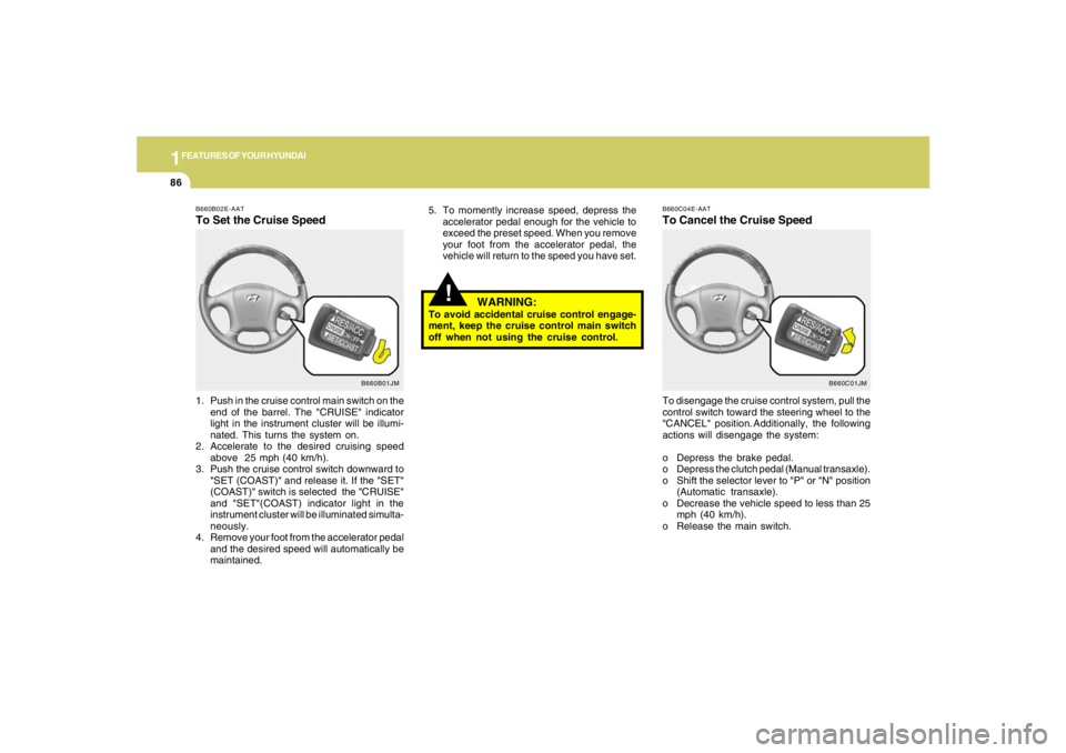
To Set the Cruise Speed1. Push in the cruise control main switch on the
end of the barrel. The "CRUISE" indicator
light in the instrument cluster will be illumi-
nated. This turns the system on.
2. Accelerate to the desired cruising speed
above 25 mph (40 km/h).
3. Push the cruise control switch downward to
"SET (COAST)" and release it. If the "SET"
(COAST)" switch is selected the "CRUISE"
and "SET"(COAST) indicator light in the
instrument cluster will be illuminated simulta-
neously.
4. Remove your foot from the accelerator pedal
and the desired speed will automatically be
maintained.
B660C01JM B660C04E-AAT
To Cancel the Cruise SpeedTo disengage the cruise control system, pull the
control switch toward the steering wheel to the
"CANCEL" position. Additionally, the following
actions will disengage the system:
o Depress the brake pedal.
o Depress the clutch pedal (Manual transaxle).
o Shift the selector lever to "P" or "N" position
(Automatic transaxle).
o Decrease the vehicle speed to less than 25
mph (40 km/h).
o Release the main switch.
Page 154 of 289
2
DRIVING YOUR HYUNDAI
3
!
!
WARNING:
o The 2WD Tucson is not designed for off-
road use. The 4WD Tucson is designed
primarily for use on paved roads. How-
ever, occasional use in off-highway con-
ditions such as established unpaved
roads and non-challenging off-road
trails is allowed. The 4WD Tucson is not
designed for blazing new trails, chal-
lenging off-road conditions, or unpaved
hill climbing. Exceeding the conditions
that were intended for the vehicle's pri-
mary design may result in injury or death.
o Utility vehicle has a significantly higher
collision rate than other type of vehicles.o Utility vehicle have higher ground clear-
ance and a narrower track to make them
capable of performing in a wide variety
of off-road applications. Specific design
characteristics give them a higher center
of gravitiy than ordinary cars. An advan-
tage of the higher ground clearance is a
better view of the road allowing you to
anticipate problem. They are not de-
signed for cornering at the same speeds
as conventional 2-wheel drive vehicles
any more than low-slung sports cars are
designed to perform satisfactorily un-
der off-road conditions. If at all possible,
avoid sharp turns or abrupt maneuvers.
As with other vehicles of this type, fail-
ure to operate this vehicle correctly may
result in loss of control or vehicle rollover.
o In a collision, an unbelted person is
significantly more likely to be seriously
injured or killed than a person wearing a
seatbelt.
WARNING:
RISK OF ROLLOVER
!
WARNING:
Your vehicle is equipped with tires de-
signed to provide for safe ride and handling
capability.
Do not use a size and type of tire and wheel
that is different from the one that is origi-
nally installed on your vehicle. It can affect
the safety and performance of your vehicle,
which could lead to handling failure or
rollover and serious injury.
When replacing the tires, be sure to equip
all four tires with the tire and wheel of the
same size, type, tread, brand and load-
carrying capacity. If you nevertheless de-
cide to equip your vehicle with any tire/
wheel combination not recommended by
Hyundai for off-road driving, you should
not use these tires for highway driving.
Page 156 of 289
2
DRIVING YOUR HYUNDAI
5
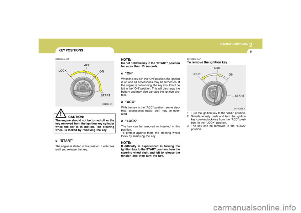
KEY POSITIONSC040A02A-AAT
CAUTION:
The engine should not be turned off or the
key removed from the ignition key cylinder
while the car is in motion. The steering
wheel is locked by removing the key.
!
o "START"The engine is started in this position. It will crank
until you release the key.
C040A01E-1
LOCKACC
ON
START
NOTE:Do not hold the key in the "START" position
for more than 15 seconds.o "ON"When the key is in the "ON" position, the ignition
is on and all accessories may be turned on. If
the engine is not running, the key should not be
left in the "ON" position. This will discharge the
battery and may also damage the ignition sys-
tem.o "ACC"With the key in the "ACC" position, some elec-
trical accessories (radio, etc.) may be oper-
ated.o "LOCK"The key can be removed or inserted in this
position.
To protect against theft, the steering wheel
locks by removing the key.NOTE:If difficulty is experienced in turning the
ignition key to the START position, turn the
steering wheel right and left to release the
tension and then turn the key.
C070C01E-1
LOCKACC
ON
START
C070C01A-AATTo remove the ignition key1. Turn the ignition key to the "ACC" position.
2. Simultaneously push and turn the ignition
key counterclockwise from the "ACC" posi-
tion to the "LOCK" position.
3. The key can be removed in the "LOCK"
position.