Page 351 of 539
1
CONTROLS AND EQUIPMENT
43
!WARNING:
o When the SRS is activated, there may be a loud noise and fine dust will be released throughout thevehicle. These conditions are normal and are not hazardous. However, the fine dust generatedduring airbag deployment may cause skin irritation. Be sure to wash your hands and face thor-oughly with lukewarm water and a mild soap after an accident in which the airbags were deployed. o The SRS can function only when
the ignition key is in the "ON"position. If the SRS SRI does not flash, or continuously remains on after flashing for about 6 secondswhen the ignition key is turned to the "ON" position or after the en- gine is started, or comes on whilstdriving, the SRS is not working properly. If this occurs, have your vehicle immediately inspected byyour Hyundai authorised repairer.
o Before you replace a fuse or dis-
connect a battery terminal, turnthe ignition key to the "LOCK" position or remove the ignition key. Never remove or replace theair bag related fuse(s) when the ignition key is in the "ON" posi- tion. Failure to heed this warningwill cause the SRS SRI to illumi- nate. B240C02HP-EAT SRS Care The SRS is virtually maintenance-free and so there are no parts you cansafely service by yourself. The entire SRS system must be inspected by a Hyundai authorised repairer 10 yearsafter the date that the vehicle was manufactured. Any work on the SRS system, such as removing, installing, repairing, or any work on the steering wheel must beperformed by a qualified Hyundai tech- nician. Improper handling of the SRS system may result in serious personalinjury.
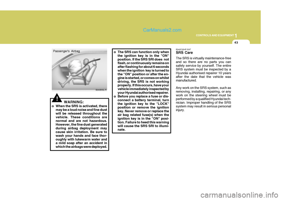
B240B05L-R
Passenger's Airbag
Page 352 of 539
1CONTROLS AND EQUIPMENT
44
!WARNING:
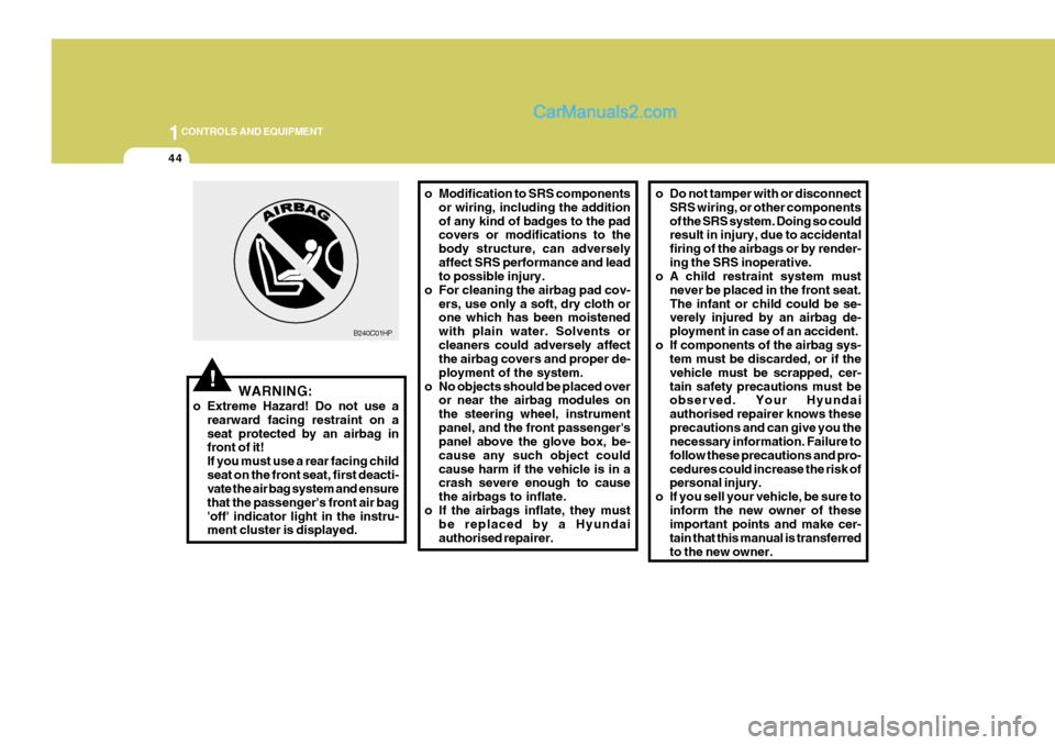
o Extreme Hazard! Do not use a rearward facing restraint on a seat protected by an airbag in front of it! If you must use a rear facing childseat on the front seat, first deacti- vate the air bag system and ensure that the passenger's front air bag'off' indicator light in the instru- ment cluster is displayed. o Modification to SRS components
or wiring, including the addition of any kind of badges to the pad covers or modifications to the body structure, can adverselyaffect SRS performance and lead to possible injury.
o For cleaning the airbag pad cov- ers, use only a soft, dry cloth orone which has been moistened with plain water. Solvents orcleaners could adversely affect the airbag covers and proper de- ployment of the system.
o No objects should be placed over or near the airbag modules onthe steering wheel, instrumentpanel, and the front passenger's panel above the glove box, be- cause any such object couldcause harm if the vehicle is in a crash severe enough to cause the airbags to inflate.
o If the airbags inflate, they must be replaced by a Hyundaiauthorised repairer.
B240C01HP
o Do not tamper with or disconnect
SRS wiring, or other components of the SRS system. Doing so could result in injury, due to accidental firing of the airbags or by render-ing the SRS inoperative.
o A child restraint system must
never be placed in the front seat.The infant or child could be se- verely injured by an airbag de- ployment in case of an accident.
o If components of the airbag sys- tem must be discarded, or if thevehicle must be scrapped, cer-tain safety precautions must be observed. Your Hyundai authorised repairer knows theseprecautions and can give you the necessary information. Failure to follow these precautions and pro-cedures could increase the risk of personal injury.
o If you sell your vehicle, be sure to inform the new owner of theseimportant points and make cer- tain that this manual is transferredto the new owner.
Page 361 of 539
1
CONTROLS AND EQUIPMENT
53
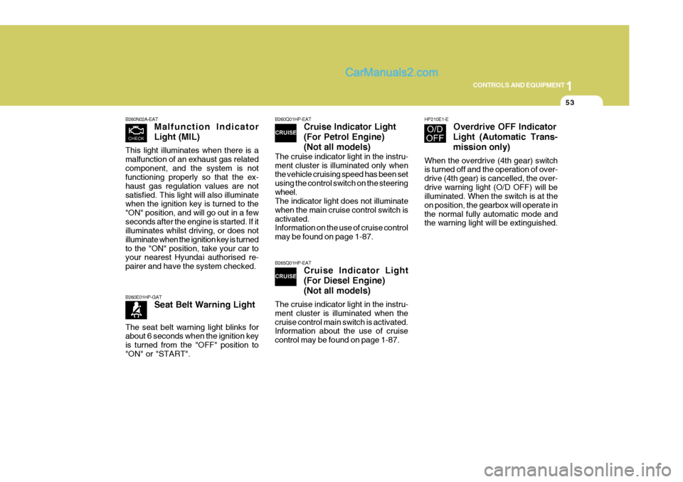
B260N02A-EAT Malfunction Indicator Light (MIL)
This light illuminates when there is a malfunction of an exhaust gas relatedcomponent, and the system is not functioning properly so that the ex- haust gas regulation values are notsatisfied. This light will also illuminate when the ignition key is turned to the "ON" position, and will go out in a fewseconds after the engine is started. If it illuminates whilst driving, or does not illuminate when the ignition key is turnedto the "ON" position, take your car to your nearest Hyundai authorised re- pairer and have the system checked.
B260Q01HP-EAT Cruise Indicator Light (For Petrol Engine)(Not all models)
The cruise indicator light in the instru- ment cluster is illuminated only when the vehicle cruising speed has been set using the control switch on the steeringwheel. The indicator light does not illuminate when the main cruise control switch isactivated. Information on the use of cruise control may be found on page 1-87.
B265Q01HP-EAT Cruise Indicator Light (For Diesel Engine) (Not all models)
The cruise indicator light in the instru- ment cluster is illuminated when thecruise control main switch is activated. Information about the use of cruise control may be found on page 1-87.
B260E01HP-GAT Seat Belt Warning Light
The seat belt warning light blinks for about 6 seconds when the ignition key is turned from the "OFF" position to"ON" or "START".
HP210E1-E Overdrive OFF Indicator
Light (Automatic Trans- mission only)
When the overdrive (4th gear) switch is turned off and the operation of over- drive (4th gear) is cancelled, the over-drive warning light (O/D OFF) will be illuminated. When the switch is at the on position, the gearbox will operate inthe normal fully automatic mode and the warning light will be extinguished.
Page 368 of 539
1CONTROLS AND EQUIPMENT
60
HPB220B1-E Lane Change Signal To indicate an intention to change lanes, moving the lever slightly towards the direction of the relevant turn signal will cause the turn signal lights to flash. Thelever will either return automatically or will need to be manually moved to the centre position when the lane changeindication has been completed.MULTI-FUNCTION SWITCH
ZB120A1-E Turn Signal Operation To signal an intention to turn right, the switch lever should be pressed down.To signal an intention to turn left, the switch lever should be pushed up- wards. In both instances, the turn sig-nal lamps the instrument cluster warn- ing light will flash. Upon completion of the manoeuvre, the lever will, undernormal circumstances, return to the "OFF" position. However, if the ma- noeuvre involved only a small move-ment of the steering wheel, the signal may need to be cancelled manually. If either turn signal indicator flashes morerapidly than normal or refuses to flash at all, a malfunction of the turn signal system may exist.
HHP2099-E
B310A03HP-E
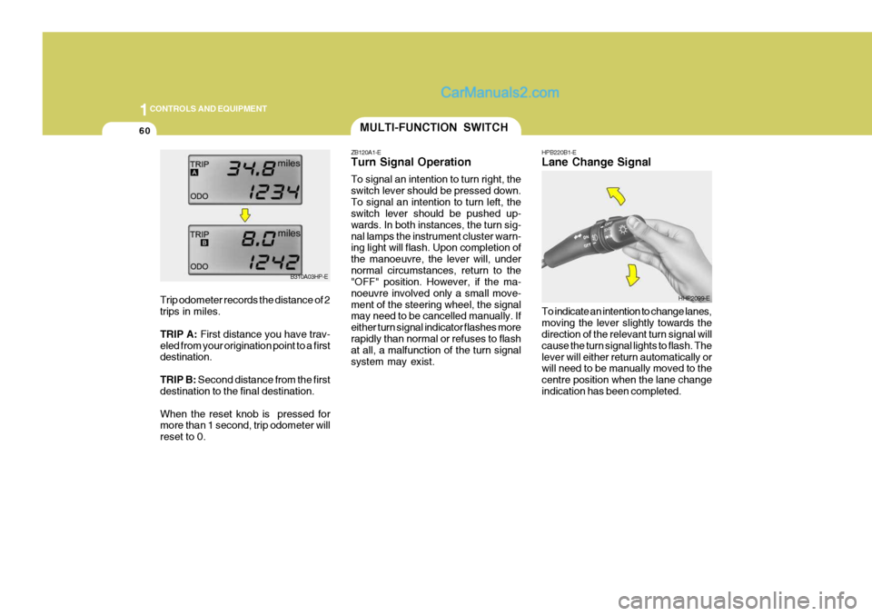
Trip odometer records the distance of 2 trips in miles. TRIP A: First distance you have trav-
eled from your origination point to a first destination. TRIP B: Second distance from the first
destination to the final destination.When the reset knob is pressed for more than 1 second, trip odometer will reset to 0.
Page 370 of 539
1CONTROLS AND EQUIPMENT
62FOG LIGHT SWITCH
B360B01Y-AAT Front Fog Light Switch To turn on the front fog lights, place the switch in the "ON" position. They will light when the headlight switch is in thefirst or second position. B360A01HP-GAT Rear Fog Light Switch
HHP2100-E B360A01HP-E
SB220E1-EHEADLIGHT FLASH The headlights may be flashed by pull- ing the turn signal switch lever towards the steering wheel. The headlights will be extinguished when the switch isreleased.
HHP2098-E
To turn on the rear fog lights, push the switch. They will light when the head- light switch is in the second position or the front fog light is turned on and thekey is in the "ON" position.
Page 371 of 539
1
CONTROLS AND EQUIPMENT
63
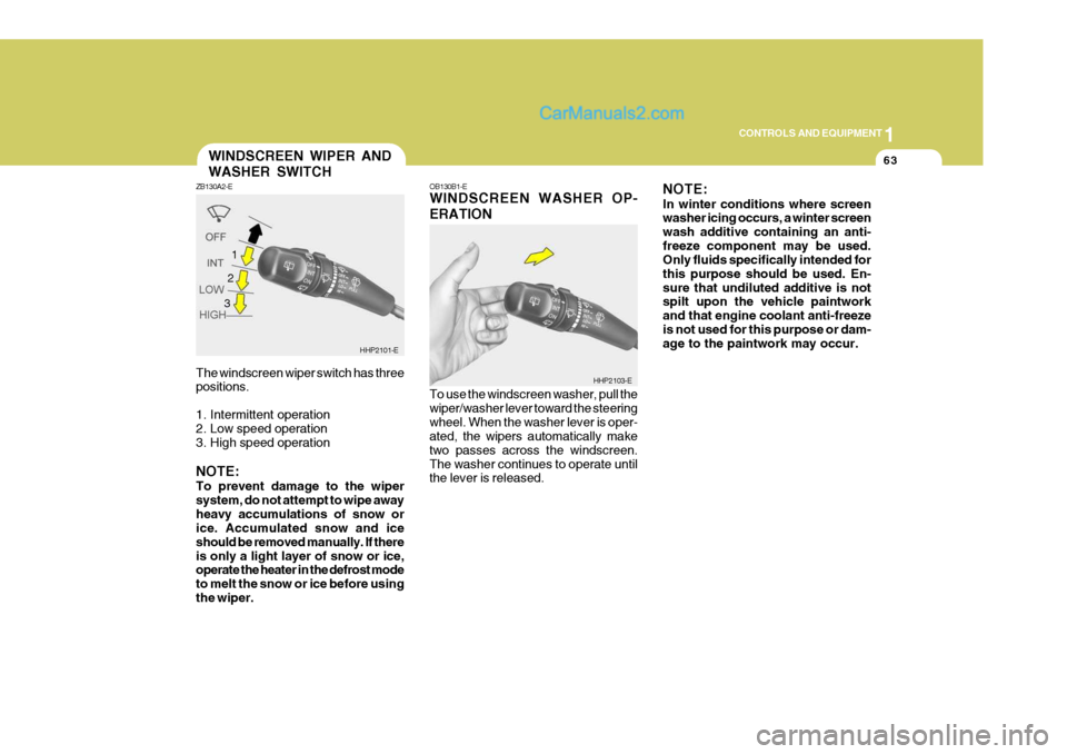
The windscreen wiper switch has three positions.
1. Intermittent operation
2. Low speed operation
3. High speed operation NOTE: To prevent damage to the wiper system, do not attempt to wipe awayheavy accumulations of snow or ice. Accumulated snow and ice should be removed manually. If thereis only a light layer of snow or ice, operate the heater in the defrost mode to melt the snow or ice before usingthe wiper.WINDSCREEN WIPER AND WASHER SWITCH
ZB130A2-E
HHP2101-E
1
OB130B1-E WINDSCREEN WASHER OP- ERATION To use the windscreen washer, pull the wiper/washer lever toward the steeringwheel. When the washer lever is oper- ated, the wipers automatically make two passes across the windscreen.The washer continues to operate until the lever is released. NOTE: In winter conditions where screen washer icing occurs, a winter screen wash additive containing an anti-freeze component may be used. Only fluids specifically intended for this purpose should be used. En-sure that undiluted additive is not spilt upon the vehicle paintwork and that engine coolant anti-freezeis not used for this purpose or dam- age to the paintwork may occur.
HHP2103-E
2 3
Page 393 of 539
1
CONTROLS AND EQUIPMENT
85
A red light comes on when the front door is opened. The purpose of this light is to assist when you get in or out and also to warn passing vehicles.FRONT DOOR EDGE WARNING LIGHT
B620A01S-EAT
B620A01HP-E
!
NOTE: The Supplemental Restraint System (SRS) label containing useful infor- mation can be found in the front ofeach sun visor.
WARNING:
Do not place the sun visor in such amanner that it obscures visibility ofthe roadway, traffic or other objects.
Press the pad on the steering wheel tosound the horn.
HHP2070
HORN
B610A01L-GAT
Page 394 of 539
1CONTROLS AND EQUIPMENT
86
!
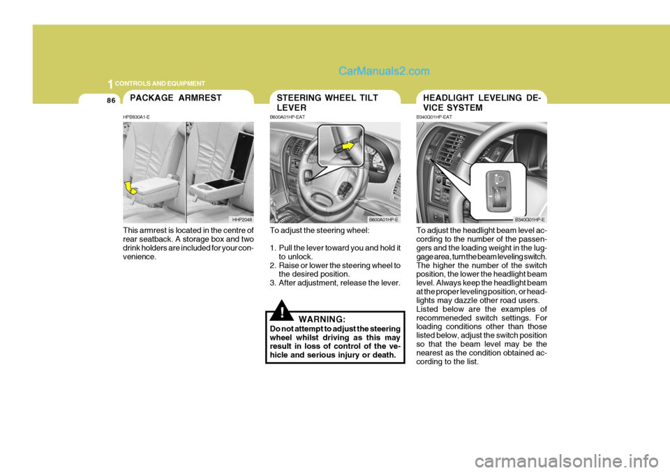
To adjust the steering wheel:
1. Pull the lever toward you and hold it
to unlock.
2. Raise or lower the steering wheel to the desired position.
3. After adjustment, release the lever.
WARNING:
Do not attempt to adjust the steering wheel whilst driving as this may result in loss of control of the ve- hicle and serious injury or death. To adjust the headlight beam level ac-cording to the number of the passen- gers and the loading weight in the lug- gage area, turn the beam leveling switch.The higher the number of the switch position, the lower the headlight beam level. Always keep the headlight beamat the proper leveling position, or head- lights may dazzle other road users. Listed below are the examples ofrecommeneded switch settings. For loading conditions other than those listed below, adjust the switch positionso that the beam level may be the nearest as the condition obtained ac- cording to the list.
STEERING WHEEL TILT LEVER
B600A01HP-EAT
B600A01HP-E
HEADLIGHT LEVELING DE- VICE SYSTEM
B340G01HP-EAT
B340G01HP-E
This armrest is located in the centre of rear seatback. A storage box and two drink holders are included for your con- venience.
PACKAGE ARMREST
HPB830A1-E
HHP2048