2006 Hyundai Terracan coolant
[x] Cancel search: coolantPage 241 of 539
6 DO-IT-YOURSELF MAINTENANCE
14CHANGING THE AIR CLEANER FILTER
!
6. Start the engine, top off the radiator
with water and then add coolant to the reservoir until the level is be- tween "LOW" and "FULL".
7. Replace the radiator and reservoir caps and check to be sure the draincocks are fully closed and not leak- ing.
WARNING:
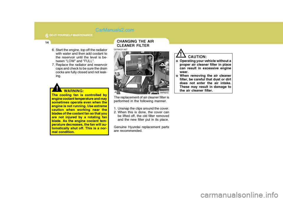
The cooling fan is controlled byengine coolant temperature and may sometimes operate even when the engine is not running. Use extremecaution when working near the blades of the coolant fan so that you are not injured by a rotating fanblade. As the engine coolant tem- perature decreases, the fan will au- tomatically shut off. This is a nor-mal condition. G070A03Y-AAT The replacement of air cleaner filter is
performed in the following manner.
1. Unsnap the clips around the cover.
2. When this is done, the cover can be lifted off, the old filter removed and the new filter put in its place.
Genuine Hyundai replacement parts
are recommended. HHP5013
!
CAUTION:
o Operating your vehicle without a proper air cleaner filter in place can result in excessive engine wear.
o When removing the air cleaner filter, be careful that dust or dirtdoes not enter the air intake. These may result in damage to the air cleaner filter.
Page 247 of 539
6 DO-IT-YOURSELF MAINTENANCE
20
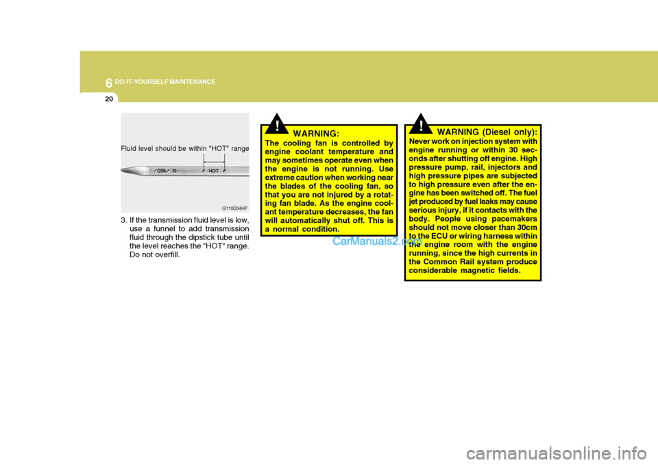
Fluid level should be within "HOT" range
3. If the transmission fluid level is low,
use a funnel to add transmission fluid through the dipstick tube until the level reaches the "HOT" range. Do not overfill. G110D04HP
!!WARNING:
The cooling fan is controlled by engine coolant temperature and may sometimes operate even whenthe engine is not running. Use extreme caution when working near the blades of the cooling fan, sothat you are not injured by a rotat- ing fan blade. As the engine cool- ant temperature decreases, the fanwill automatically shut off. This is a normal condition. WARNING (Diesel only):
Never work on injection system with
engine running or within 30 sec- onds after shutting off engine. High pressure pump, rail, injectors and high pressure pipes are subjectedto high pressure even after the en- gine has been switched off. The fuel jet produced by fuel leaks may causeserious injury, if it contacts with the body. People using pacemakers should not move closer than 30cmto the ECU or wiring harness within the engine room with the engine running, since the high currents inthe Common Rail system produce considerable magnetic fields.
Page 260 of 539
6
DO-IT-YOURSELF MAINTENANCE
33
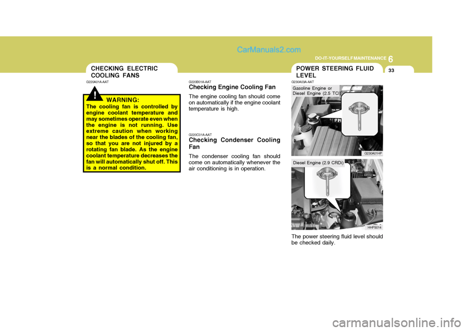
Gasoline Engine or Diesel Engine (2.5 TCI)
POWER STEERING FLUID LEVEL
G220B01A-AAT
Checking Engine Cooling Fan
The engine cooling fan should come
on automatically if the engine coolant temperature is high.
G220C01A-AAT
Checking Condenser Cooling Fan
The condenser cooling fan should
come on automatically whenever the air conditioning is in operation. G230A03A-AAT The power steering fluid level should be checked daily.G230A01HP
HHP5014CHECKING ELECTRIC COOLING FANS
!
G220A01A-AAT WARNING:
The cooling fan is controlled by
engine coolant temperature and may sometimes operate even whenthe engine is not running. Use extreme caution when working near the blades of the cooling fan,so that you are not injured by a rotating fan blade. As the engine coolant temperature decreases thefan will automatically shut off. This is a normal condition.
Diesel Engine (2.9 CRDi)
Page 267 of 539
6 DO-IT-YOURSELF MAINTENANCE
40
1. Keep all tires inflated to the correct
pressure.
2. Place the vehicle on level ground and press the front bumper & rear bumper down several times. Placevehicle at a distance of 3m (118.1 in.) from the test wall.
3. See that the vehicle is unloaded (except for full levels of coolant, engine oil and fuel, and spare tire,jack, and tools). Have the driver or equivalent weight placed in driver's seat.
4. Clean the headlight lens and turn on the headlight.
5. Open the hood.
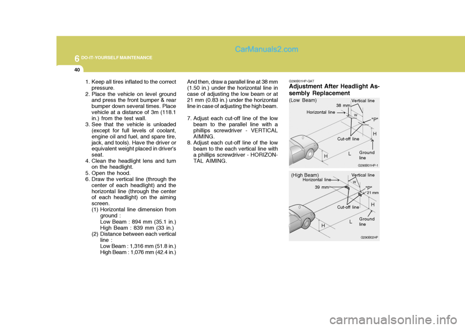
6. Draw the vertical line (through the center of each headlight) and thehorizontal line (through the center of each headlight) on the aiming screen.
(1) Horizontal line dimension from
ground : Low Beam : 894 mm (35.1 in.) High Beam : 839 mm (33 in.)
(2) Distance between each vertical line : Low Beam : 1,316 mm (51.8 in.) High Beam : 1,076 mm (42.4 in.) And then, draw a parallel line at 38 mm
(1.50 in.) under the horizontal line incase of adjusting the low beam or at 21 mm (0.83 in.) under the horizontal line in case of adjusting the high beam.
7. Adjust each cut-off line of the low beam to the parallel line with a phillips screwdriver - VERTICAL AIMING.
8. Adjust each cut-off line of the low beam to the each vertical line witha phillips screwdriver - HORIZON-TAL AIMING. G290B01HP-GAT
Adjustment After Headlight As- sembly Replacement
G290B02HP
LW
H Cut-off line
"P"
Vertical line
Horizontal line
Ground line
21 mm39 mm
(High Beam)
H
G290B01HP-1
LW
"P"
38 mm
H
H
(Low Beam)
Vertical line
Ground line
Cut-off line
Horizontal line
Page 276 of 539
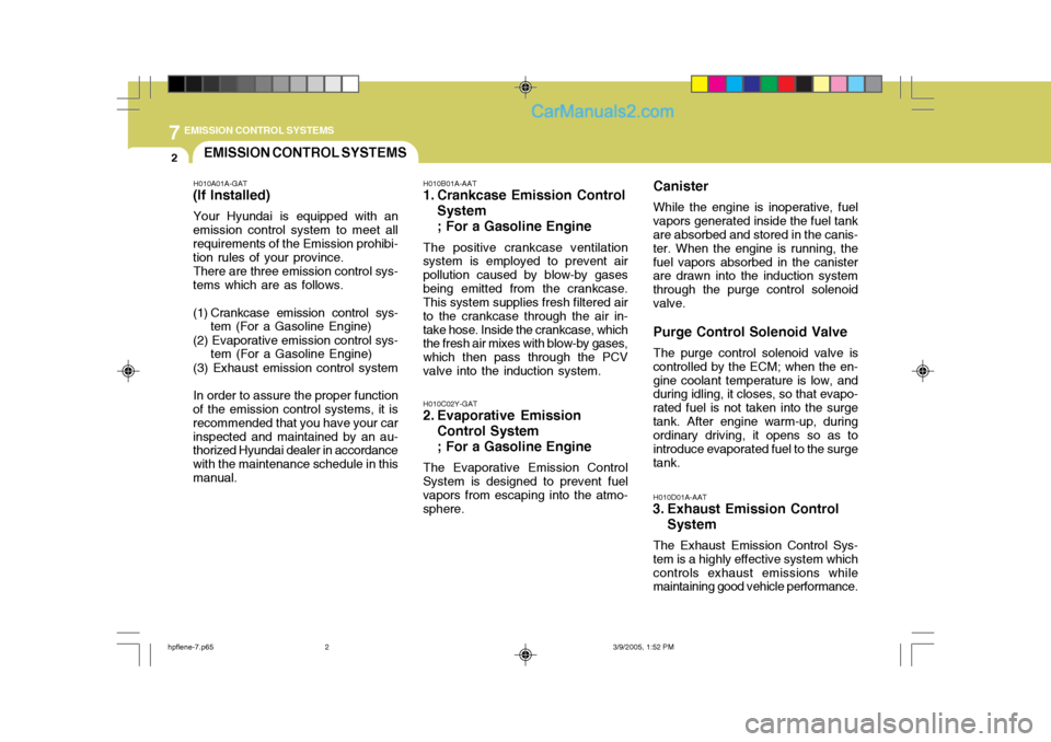
7EMISSION CONTROL SYSTEMS
2EMISSION CONTROL SYSTEMS
H010A01A-GAT
(If Installed)
Your Hyundai is equipped with an
emission control system to meet all requirements of the Emission prohibi- tion rules of your province.
There are three emission control sys-
tems which are as follows.
(1) Crankcase emission control sys- tem (For a Gasoline Engine)
(2) Evaporative emission control sys- tem (For a Gasoline Engine)
(3) Exhaust emission control system
In order to assure the proper function
of the emission control systems, it is recommended that you have your carinspected and maintained by an au- thorized Hyundai dealer in accordance with the maintenance schedule in thismanual. H010B01A-AAT
1. Crankcase Emission Control
System ; For a Gasoline Engine
The positive crankcase ventilation
system is employed to prevent air pollution caused by blow-by gasesbeing emitted from the crankcase. This system supplies fresh filtered air to the crankcase through the air in-take hose. Inside the crankcase, which the fresh air mixes with blow-by gases, which then pass through the PCVvalve into the induction system.
H010C02Y-GAT
2. Evaporative Emission
Control System ; For a Gasoline Engine
The Evaporative Emission Control
System is designed to prevent fuel vapors from escaping into the atmo- sphere. Canister
While the engine is inoperative, fuel
vapors generated inside the fuel tankare absorbed and stored in the canis- ter. When the engine is running, thefuel vapors absorbed in the canister are drawn into the induction system through the purge control solenoidvalve. Purge Control Solenoid Valve
The purge control solenoid valve is
controlled by the ECM; when the en- gine coolant temperature is low, and during idling, it closes, so that evapo- rated fuel is not taken into the surgetank. After engine warm-up, during ordinary driving, it opens so as to introduce evaporated fuel to the surgetank. H010D01A-AAT
3. Exhaust Emission Control
System
The Exhaust Emission Control Sys- tem is a highly effective system whichcontrols exhaust emissions while maintaining good vehicle performance.
hpflene-7.p65 3/9/2005, 1:52 PM
2
Page 291 of 539
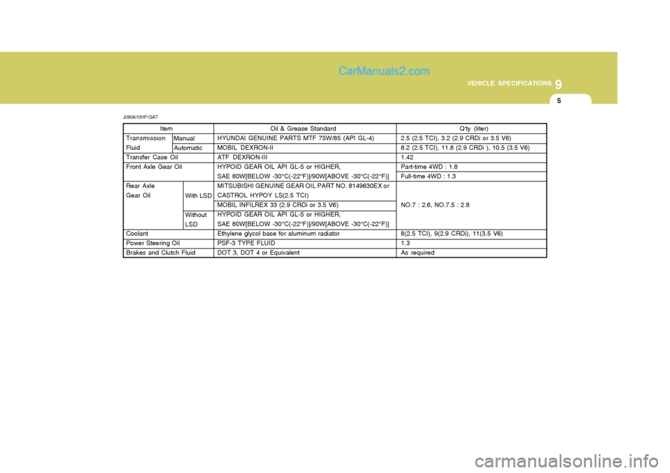
9
VEHICLE SPECIFICATIONS
5
J080A10HP-GAT Item
Transmission FluidTransfer Case OilFront Axle Gear Oil Rear Axle Gear Oil Coolant Power Steering OilBrakes and Clutch Fluid Oil & Grease Standard
HYUNDAI GENUINE PARTS MTF 75W/85 (API GL-4)MOBIL DEXRON-IIATF DEXRON-IIIHYPOID GEAR OIL API GL-5 or HIGHER,SAE 80W[BELOW -30°C(-22°F)]/90W[ABOVE -30°C(-22°F)]MITSUBISHI GENUINE GEAR OIL PART NO. 8149630EX orCASTROL HYPOY LS(2.5 TCI)MOBIL INFILREX 33 (2.9 CRDi or 3.5 V6)HYPOID GEAR OIL API GL-5 or HIGHER,SAE 80W[BELOW -30°C(-22°F)]/90W[ABOVE -30°C(-22°F)]Ethylene glycol base for aluminum radiatorPSF-3 TYPE FLUIDDOT 3, DOT 4 or Equivalent
Q'ty (liter)
2.5 (2.5 TCI), 3.2 (2.9 CRDi or 3.5 V6) 8.2 (2.5 TCI), 11.8 (2.9 CRDi ), 10.5 (3.5 V6)1.42Part-time 4WD : 1.8Full-time 4WD : 1.3 NO.7 : 2.6, NO.7.5 : 2.88(2.5 TCI), 9(2.9 CRDi), 11(3.5 V6) 1.3As required
Manual Automatic
With LSD Without LSD
Page 294 of 539

10
INDEX
3
Corrosion protection Cleaning the interior ................................................. 4-6
Protecting your Hyundai from corrosion .................. 4-2
Washing and waxing ................................................ 4-4
Cruise Control ......................................................... 1-100
D Defrosting/Defogging ............................................... 1-109
Door
Locking and unlocking front door with a key .......... 1-11
Drink Holder ............................................................... 1-81
Drive Belts ........................................................ 6-23, 6-27
Driving
Driving for econom y ............................................... 2-23
Smooth cornering ................................................... 2-25
Winter driving ......................................................... 2-25
E Emission Control Syst em ........................................... 7-1
Catalytic converter ................................................... 7-3
EGR System ............................................................ 7-5
Engine Before starting the engine ....................................... 2-3 Compartment (3.5 V6) ............................................. 6-2
Compartment (2.5 TCI) ............................................ 6-3
Compartment (2.9 CRDi) ......................................... 6-4 Coolant ................................................................... 6-11
Coolant temper ature gauge ................................... 1-65If the engine
overheats ............................................. 3-4
Number ..................................................................... 8-2
Oil ............................................................................. 6-6 Starting ..................................................................... 2-5
Engine Exhaust Can Be Dangerous ............................ 2-2
FFan Speed Control ...................................... 1-104, 1-115
Fog Light Switch
Front ....................................................................... 1-75
Rear ....................................................................... 1-75
Four-Wheel Drive (4WD) ............................................ 2-14
Front Seats
Adjustable front seats ............................................ 1-18
Adjustable headrest s .............................................. 1-19
Adjusting seat forward and rear ward..................... 1-18
Adjusting seatback angle .......................................1-19
Front/Rear Window Defroster Sw itch....................... 1-78
Fuel
Capacity ................................................................... 9-2
Diesel ....................................................................... 1-2
Gauge .................................................................... 1-65
Unleaded gasolin e ................................................... 1-2
Fuel Filler Lid Remote release ...................................................... 1-95
Full-time 4WD Operation ............................................ 2-17
Fuses ........................................................................ 6-28
Page 311 of 539

1
CONTROLS AND EQUIPMENT
3
ZB010C1-E "Alternative fuels" Fuels which contain methanol or etha- nol must not be used. ZB010D1-E Operation in Foreign Countries Drivers of vehicles which are to be operated in foreign countries must satisfy themselves that:
o The vehicle meets all local regula- tions with respect to insurance, speci- fications etc..
o The correct types and grades of fuel
are available for satisfactory opera-tion of the vehicle.
ZB010F2-A FUELS FOR CLEANER AIR To help contribute to cleaner air, Hyundai recommends that you use fuels treated with detergent additives, which help to prevent deposit forma-tion in the engine. These fuels will help the engines run cleaner and increase the Emission Control System perfor-mance.BEFORE ENTERING THE VE- HICLE
YB020A1-E
o Ensure that all windows, mirrors
and lamps are clean.
o Check condition of all tyres.
o Ensure that no fluid leaks are evi-
dent.
o Ensure that the area around the
vehicle is clear before driving off.AFTER ENTERING THE VE- HICLE
YB020B1-E
o Ensure that all occupants fasten
and correctly adjust seat belts.
o Ensure that seat and head restraint
positions are adjusted for optimum safety, control and comfort.
o Adjust interior and exterior rearview
mirrors.
o Verify correct operation of lamps, horn and other electrical equipment.
o Ensure that warning lamps illumi- nate when ignition is turned on.
NOTE: Fluid levels such as engine oil, en- gine coolant, brake and windscreenwasher fluid should be checked daily or at each refuelling, whichever occurs sooner.