2006 Hyundai Terracan fuse
[x] Cancel search: fusePage 273 of 539
6 DO-IT-YOURSELF MAINTENANCE
46
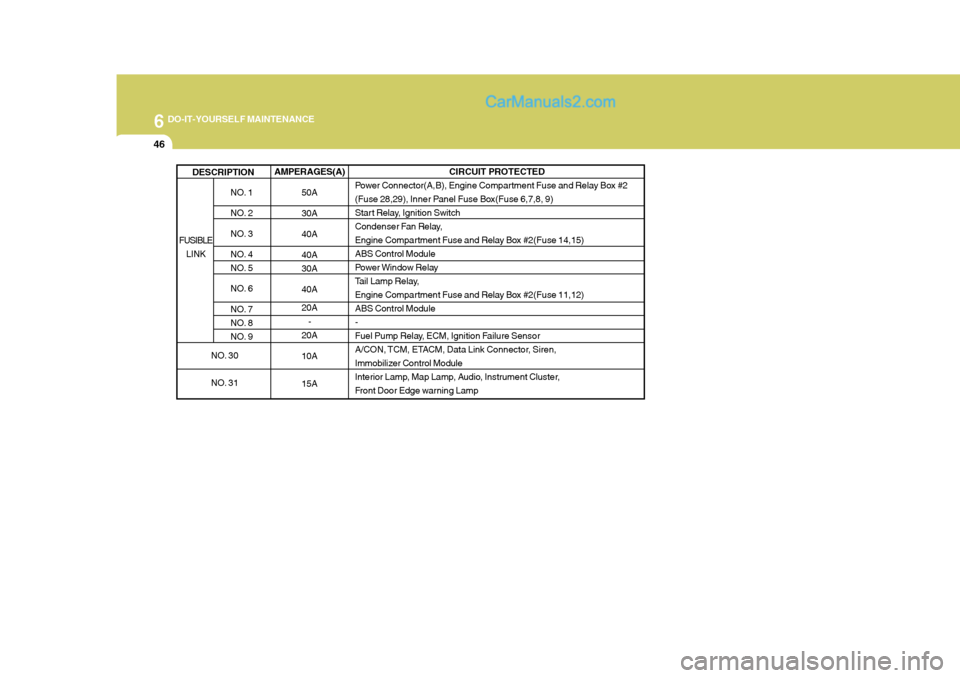
AMPERAGES(A)50A 30A 40A 40A 30A 40A 20A-
20A 10A 15A
NO. 1
NO. 2
NO. 3
NO. 4
NO. 5
NO. 6
NO. 7
NO. 8
NO. 9
DESCRIPTION
CIRCUIT PROTECTED
Power Connector(A,B), Engine Compartment Fuse and Relay Box #2
(Fuse 28,29), Inner Panel Fuse Box(Fuse 6,7,8, 9)
Start Relay, Ignition Switch
Condenser Fan Relay,
Engine Compartment Fuse and Relay Box #2(Fuse 14,15)ABS Control Module
Power Window Relay
Tail Lamp Relay,
Engine Compartment Fuse and Relay Box #2(Fuse 11,12)ABS Control Module-
Fuel Pump Relay, ECM, Ignition Failure Sensor
A/CON, TCM, ETACM, Data Link Connector, Siren,
Immobilizer Control Module
Interior Lamp, Map Lamp, Audio, Instrument Cluster,
Front Door Edge warning Lamp
FUSIBLE LINK
NO. 30
NO. 31
Page 274 of 539

6
DO-IT-YOURSELF MAINTENANCE
47
NO. 1 2 34 5 67 8 9
10 11 1213 14 1516 17 1819 20 2122 23 2425 26 2728 AMPERAGES(A)
30A 10A 15A 20A10A15A30A20A 10A 10A20A10A- -
10A 10A -
10A10A10A10A 10A 10A
-
10A15A15A 10A CIRCUIT PROTECTED
Defogger Relay
Hazard Relay, Hazard Switch Stop Lamp Switch
TOD, EST Control Module - Sunroof Controller
Blower Relay
Power Door Locks
Rear Fog Lamp Relay
Audio, Map Lamp
Cigarette Lighter, Power Outlet relay, ACC Socket
Power Outside Mirror Switch- - A/C Switch
Left/Right Outside Mirror & Defogger -
TCM, ECM(COVEC-F), TCCS(TOD, EST), Immobilizer
Back-up Lamp Switch, Inside Rearview Mirror, Transmission Range Switch Hazard Switch
Instrument Cluster, ETACM, Vehicle Speed Sensor, DRL Control ModuleAirbag Airbag Indicator -
Blower & A/C, ETACM, Defogger Relay
Seat Warmer
Sunroof, Rear Wiper & Washer, Cruise Switch, Rear Intermittent Wiper Relay
Start Relay, Theft-Alarm Relay
G200E01HP-GAT
Inner Panel
Note: Not all fuse panel descriptions in this manual may be applicable to your vehicle. It is accurate at the time of printing. When you inspect the fuse box on your vehicle, refer to the fuse box label. G200D01HP
Page 294 of 539

10
INDEX
3
Corrosion protection Cleaning the interior ................................................. 4-6
Protecting your Hyundai from corrosion .................. 4-2
Washing and waxing ................................................ 4-4
Cruise Control ......................................................... 1-100
D Defrosting/Defogging ............................................... 1-109
Door
Locking and unlocking front door with a key .......... 1-11
Drink Holder ............................................................... 1-81
Drive Belts ........................................................ 6-23, 6-27
Driving
Driving for econom y ............................................... 2-23
Smooth cornering ................................................... 2-25
Winter driving ......................................................... 2-25
E Emission Control Syst em ........................................... 7-1
Catalytic converter ................................................... 7-3
EGR System ............................................................ 7-5
Engine Before starting the engine ....................................... 2-3 Compartment (3.5 V6) ............................................. 6-2
Compartment (2.5 TCI) ............................................ 6-3
Compartment (2.9 CRDi) ......................................... 6-4 Coolant ................................................................... 6-11
Coolant temper ature gauge ................................... 1-65If the engine
overheats ............................................. 3-4
Number ..................................................................... 8-2
Oil ............................................................................. 6-6 Starting ..................................................................... 2-5
Engine Exhaust Can Be Dangerous ............................ 2-2
FFan Speed Control ...................................... 1-104, 1-115
Fog Light Switch
Front ....................................................................... 1-75
Rear ....................................................................... 1-75
Four-Wheel Drive (4WD) ............................................ 2-14
Front Seats
Adjustable front seats ............................................ 1-18
Adjustable headrest s .............................................. 1-19
Adjusting seat forward and rear ward..................... 1-18
Adjusting seatback angle .......................................1-19
Front/Rear Window Defroster Sw itch....................... 1-78
Fuel
Capacity ................................................................... 9-2
Diesel ....................................................................... 1-2
Gauge .................................................................... 1-65
Unleaded gasolin e ................................................... 1-2
Fuel Filler Lid Remote release ...................................................... 1-95
Full-time 4WD Operation ............................................ 2-17
Fuses ........................................................................ 6-28
Page 351 of 539
1
CONTROLS AND EQUIPMENT
43
!WARNING:
o When the SRS is activated, there may be a loud noise and fine dust will be released throughout thevehicle. These conditions are normal and are not hazardous. However, the fine dust generatedduring airbag deployment may cause skin irritation. Be sure to wash your hands and face thor-oughly with lukewarm water and a mild soap after an accident in which the airbags were deployed. o The SRS can function only when
the ignition key is in the "ON"position. If the SRS SRI does not flash, or continuously remains on after flashing for about 6 secondswhen the ignition key is turned to the "ON" position or after the en- gine is started, or comes on whilstdriving, the SRS is not working properly. If this occurs, have your vehicle immediately inspected byyour Hyundai authorised repairer.
o Before you replace a fuse or dis-
connect a battery terminal, turnthe ignition key to the "LOCK" position or remove the ignition key. Never remove or replace theair bag related fuse(s) when the ignition key is in the "ON" posi- tion. Failure to heed this warningwill cause the SRS SRI to illumi- nate. B240C02HP-EAT SRS Care The SRS is virtually maintenance-free and so there are no parts you cansafely service by yourself. The entire SRS system must be inspected by a Hyundai authorised repairer 10 yearsafter the date that the vehicle was manufactured. Any work on the SRS system, such as removing, installing, repairing, or any work on the steering wheel must beperformed by a qualified Hyundai tech- nician. Improper handling of the SRS system may result in serious personalinjury.
B240B05L-R
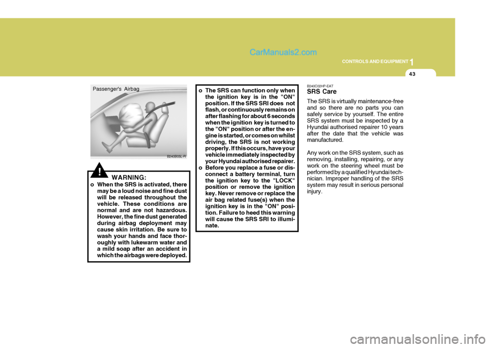
Passenger's Airbag
Page 368 of 539
1CONTROLS AND EQUIPMENT
60
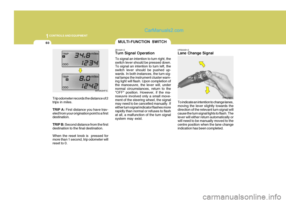
HPB220B1-E Lane Change Signal To indicate an intention to change lanes, moving the lever slightly towards the direction of the relevant turn signal will cause the turn signal lights to flash. Thelever will either return automatically or will need to be manually moved to the centre position when the lane changeindication has been completed.MULTI-FUNCTION SWITCH
ZB120A1-E Turn Signal Operation To signal an intention to turn right, the switch lever should be pressed down.To signal an intention to turn left, the switch lever should be pushed up- wards. In both instances, the turn sig-nal lamps the instrument cluster warn- ing light will flash. Upon completion of the manoeuvre, the lever will, undernormal circumstances, return to the "OFF" position. However, if the ma- noeuvre involved only a small move-ment of the steering wheel, the signal may need to be cancelled manually. If either turn signal indicator flashes morerapidly than normal or refuses to flash at all, a malfunction of the turn signal system may exist.
HHP2099-E
B310A03HP-E
Trip odometer records the distance of 2 trips in miles. TRIP A: First distance you have trav-
eled from your origination point to a first destination. TRIP B: Second distance from the first
destination to the final destination.When the reset knob is pressed for more than 1 second, trip odometer will reset to 0.
Page 448 of 539
3 IN CASE OF EMERGENCY
2
!WARNING:
If the engine refuses to start, no attempt should be made to push or tow start the vehicle. Vehicles with automatic transmission or fuel in-jection will not be able to be started in this manner since no drive is transmitted through the automatictransmission whilst the engine is not running, and in the case of fuel injected derivatives, the fuel pumpwill not operate under tow start conditions. In addition, if the ve- hicle is equipped with an exhaustcatalyst, damage to the catalyst may result if the vehicle is tow started. HPD020B1-E If The Engine Cannot Be Cranked
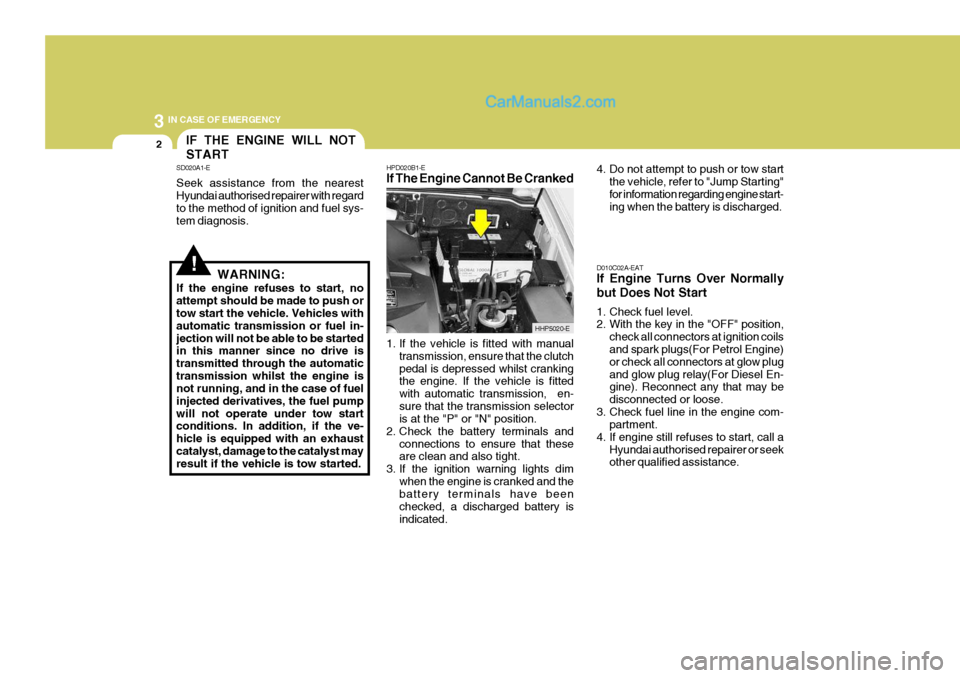
1. If the vehicle is fitted with manual
transmission, ensure that the clutch pedal is depressed whilst cranking the engine. If the vehicle is fitted with automatic transmission, en-sure that the transmission selector is at the "P" or "N" position.
2. Check the battery terminals and
connections to ensure that theseare clean and also tight.
3. If the ignition warning lights dim
when the engine is cranked and thebattery terminals have been checked, a discharged battery isindicated. 4. Do not attempt to push or tow start
the vehicle, refer to "Jump Starting"for information regarding engine start- ing when the battery is discharged.
D010C02A-EAT If Engine Turns Over Normally but Does Not Start
1. Check fuel level.
2. With the key in the "OFF" position, check all connectors at ignition coilsand spark plugs(For Petrol Engine) or check all connectors at glow plugand glow plug relay(For Diesel En- gine). Reconnect any that may be disconnected or loose.
3. Check fuel line in the engine com- partment.
4. If engine still refuses to start, call a Hyundai authorised repairer or seek other qualified assistance.
IF THE ENGINE WILL NOT START
SD020A1-E Seek assistance from the nearest Hyundai authorised repairer with regard to the method of ignition and fuel sys- tem diagnosis.
HHP5020-E
Page 479 of 539
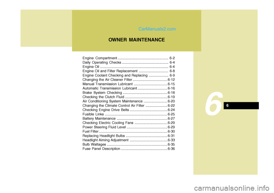
Engine Compartment ................................................... 6-2
Daily Operating Checks ............................................... 6-4
Engine Oil ..................................................................... 6-4
Engine Oil and Filter Replacement .............................. 6-8
Engine Coolant Checking and Replacing .................... 6-9
Changing the Air Cleaner Filter ...................................6-12
Manual Transmission Lubricant ..................................6-15
Automatic Transmission Lubricant ..............................6-16
Brake System Checking ............................................. 6-18
Checking the Clutch Fluid ........................................... 6-19
Air Conditioning System Maintenance ........................ 6-20
Changing the Climate Control Air Filter .. ....................6-22
Checking Engine Drive Belts ...................................... 6-24
Fusible Links ............................................................... 6-25
Battery Mai ntenance ................................................... 6-27
Checking Electric Cooling Fans .................................6-29
Power Steering Fluid Level ......................................... 6-29
Fuel Filter ..................................................................... 6-30
Replacing Headlight Bulbs .......................................... 6-31
Headlight Aiming Adjustment ...................................... 6-33
Bulb Wattages ............................................................. 6-35
Fuse Panel D escription ............................................... 6-36
OWNER MAINTENANCE
6
6
Page 480 of 539

6 OWNER MAINTENANCE
2
1. Power steering fluid reservoir 2. Brake fluid reservoir 3. Engine cover 4. Battery 5. Fuse and relay box 6. Windscreen washer fluid reservoir
7. Air cleaner filter
8. Radiator cap
9. Engine oil filler cap
10. Automatic transmission fluid level
dipstick (Vehicle with automatictransmission)
11. Engine oil level dipstick
12. Coolant reservoir cap
G010A01HP-EAT Petrol Engine Compartment (3.5 V6)
CAUTION:
When inspecting or servic-
ing the engine, you should handle tools and other heavy objects carefully so that the plastic cover of theengine is not damaged.
!
ENGINE COMPARTMENT
G010A01HP-E