2006 Hyundai Matrix stop start
[x] Cancel search: stop startPage 216 of 490

6 DO-IT-YOURSELF MAINTENANCE
10
CAUTION:
Slowly pour the recommended oil into a funnel. Do not overfill not todamage engine.
!
NOTE: Always dispose of used engine oil in an environmentally acceptablemanner. It is suggested that it be placed in a sealed container and taken to a service station for maybereclaimation. Do not pour the oil on the ground or put it in with the household trash.
Be sure that the mounting surfaceon the engine is clean and that theold gasket is removed completely. Lubricate the new gasket on the filter with clean engine oil beforeinstallation.
7. Remove the engine oil level dip- stick.
8. Refill the crankcase with the rec-
ommended engine oil. Refer tothe specification in chapter 9 for engine oil capacity.
!
9. Start the engine and check to be sure no oil is leaking from the drain plug or oil filter.
10.Shut off the engine and recheck the oil level. WARNING:
Used motor oil may cause irrita-
tion or cancer of the skin if left in contact with the skin for prolongedperiods of time. Wash your hands thoroughly with soap and warm water as soon as possible afterhandling used oil.
4. When the oil has stopped draining,
replace the drain plug using a newgasket and retighten by turning it clockwise. Oil pan drain plug tightening torque :
1.6 DOHC 1.8 DOHC 4.0 ~ 4.5 3.5 ~ 4.5
E.CExcept E.C
4.0 ~ 4.5 kgf.m
5. Remove the oil filter by turning it counterclockwise with a oil filter wrench of the proper size. A cer-tain amount of oil will come out when you remove the filter. So be sure to have your drain pan inplace underneath it.
6. Install a new oil filter in accordance with the instructions on the cartonor on the filter itself. Do not over- tighten. Oil filter tightening torque: 1.2~1.6kgf.m
Page 217 of 490

6
DO-IT-YOURSELF MAINTENANCE
11
G040B04FC-GAT
Diesel Engine
Oil filter
G040B01FC
Oil filler cap
The engine oil and filter should be changed at those intervals specifiedin the maintenance schedule in Sec- tion 5. If the car is being driven in severe conditions, more frequent oiland filter changes are required. The procedure for changing the oil and filter is as follows:
1. Park the car on level ground and set the parking brake. Start the engine and let it warm up until the needle on the coolant temperature gauge moves above the lowestmark.
!
Centerpipe O-ring
G040B02FC
Upper capO-ring
Oil filter element
Oil filter housing
Turn the engine off and place the gear selector lever in "P" (auto-matic) or reverse gear (manual transaxle).
2. Open the hood and remove the engine oil level dipstick.
3. Loosen the oil filter upper cap with a proper tool from the oil filter housing until an O-ring is seen.Then, drain the oil completely. 4. Remove the engine oil filler cap.
5. Slide underneath the car and
loosen the oil pan drain plug by turning it counterclockwise oil pan with a wrench of the proper size. Be sure that a drain pan is inposition to catch the oil as it drains out, then remove the drain plug.
WARNING:
Be very careful when draining the engine oil as it may be hot enoughto burn you!
6. When the oil has stopped draining, replace the drain plug using a new gasket and retighten by turning it clockwise.
Oil pan drain plug tightening torque : 3.5 ~ 4.5 kgf.m
7. Pull out the oil filter upper cap with element from the oil filter housing. Using a clean cloth, remove any dirt or oil accumulated around the oil filter housing.
! CAUTION:
Slowly loosen the oil filter upper cap not to overflow the oil.
Page 238 of 490

6 DO-IT-YOURSELF MAINTENANCE
32
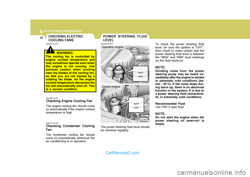
To check the power steering fluid level, be sure the ignition is "OFF",then check to make certain that the power steering fluid level is between the "MAX" and "MIN" level markingson the fluid reservoir. NOTE: Grinding noise from the power steering pump may be heard im- mediately after the engine is startedin extremely cold conditions (be- low - 20°C). If the noise stops dur- ing warm up, there is no abnormalfunction in the system. It is due to a power steering fluid characteris- tic in extremely cold conditions. Recommended Fluid Use PSF-3 type fluid NOTE: Do not start the engine when the power steering oil reservoir is empty.
!
CHECKING ELECTRIC COOLING FANS
G220A01A-AAT
WARNING:
The cooling fan is controlled by engine coolant temperature and may sometimes operate even whenthe engine is not running. Use extreme caution when working near the blades of the cooling fan,so that you are not injured by a rotating fan blade. As the engine coolant temperature decreases thefan will automatically shut off. This is a normal condition.POWER STEERING FLUID LEVEL
G220B01A-AAT
Checking Engine Cooling Fan
The engine cooling fan should come on automatically if the engine coolant temperature is high. G220C01A-AAT
Checking Condenser Cooling Fan
The condenser cooling fan should come on automatically whenever the air conditioning is in operation. G230A03A-GAT
HFC5004
G230A02FC
Gasoline engine
Diesel engine
The power steering fluid level should be checked regularly.
Page 245 of 490

6
DO-IT-YOURSELF MAINTENANCE
39FUSE PANEL DESCRIPTION
G200C03FC-GAT
Engine Compartment (Gasoline Engine)
G200C03FC
NOTE: Not all fuse panel descriptions in this manual may be applicable to your vehicle. It is accurate at the time of printing. When you inspect the fuse box on your vehicle, refer to the fuse box label.
PROTECTED COMPONENTS
Generator (A/CON, RR HTD, STOP, D/LOCK, HAZARD) Fuse Generator, Engine control relay, ECM Radiator fan relay Start relay, Ignition switch Blower relay Power window relay Condenser fan relay #1 ABS control module, ABS bleeding connector, ESP ABS control module, ABS bleeding connector, ESP Fuel pump relay Injector, lgnition coil MAP sensor, Oxygen sensor, CP sensor, Knock sensor, Throttle position sensor Audio, Room lamp, Overhead console lamp, lnstrument cluster DRL control module Horn relay A/C relay Front fog lamp relay ECM, TCM Tail lamp relay Left rear combi lamp, Left position lamp, Left License lamp Right rear combi lamp, Right position lamp, Right License lamp Left head lamp Right head lamp, (H/LP IND) Fuse
FUSE RATING
120A
40A 30A 20A 40A 40A 30A 20A 40A 40A 10A 15A 10A10A 15A 10A 10A 15A 10A 20A 10A 10A 15A 15A
DESCRIPTION
ALTB+
ECU RAD IGN
BLR
P/WIN
COND
ABSABS
F/PUMP INJ
SNSR
ROOM LP DRL
HORN
A/CON
FR FOG ECU
LP
TAIL LH
TAIL RH H/LP LH
H/LP RH
Page 247 of 490

6
DO-IT-YOURSELF MAINTENANCE
41
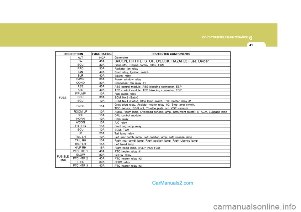
ALT B+
ECU RAD
IGN
BLR
P/WIN
COND ABSABS
F/PUMP ECU ECU
SNSR
ROOM LP DRL
HORN
A/CON
FR FOG ECU
LP
TAIL LH
TAIL RH H/LP LH
H/LP RH
PTC HTR 1
GLOW
PTC HTR 2 FFHS
PTC HTR 3 PROTECTED COMPONENTS
Generator (A/CON, RR HTD, STOP, D/LOCK, HAZARD) Fuse, Deicer Generator, Engine control relay, ECM Radiator fan relayStart relay, Ignition switchBlower relayPower window relayCondenser fan relay #1 ABS control module, ABS bleeding connector, ESP ABS control module, ABS bleeding connector, ESPFuel pump relayECM No.5 (Batt+)ECM No.4 (Batt+), Stop lamp switch, PTC heater relay #1Glow plug relay, Assistor heater relay 1/2, Stop lamp switch, TDC sensor, EGR act, Throttle plate act, VGT vacuum Audio, Room lamp, Overhead console lamp, lnstrument cluster, ETACM, Luggage lampDRL control moduleHorn relayA/C relayFront fog lamp relay ECM, TCM Tail lamp relayLeft rear combi lamp, Left position lamp, Left License lampRight rear combi lamp, Right position lamp, Right License lampLeft head lampRight head lamp, (H/LP IND) Fuse PTC heater relay #1 GLOW relayPTC heater relay #2FFHS relayPTC heater relay #3
FUSE RATING
140A40A30A30A40A40A 30A 30A40A40A10A30A 10A 15A 10A 15A10A10A 15A 10A20A10A10A15A 15A 40A80A40A30A40A
FUSE
FUSIBLE LINK DESCRIPTION
Page 248 of 490

6 DO-IT-YOURSELF MAINTENANCE
42
G200D01FC-GAT Inner Panel
G200D01FC
DESCRIPTIONH/LP IND
HTD IND
A/CON
RR HTD STOP
D/LOCK
HAZARD AUDIO
C/LIGHT A/B
A/B IND
T/SIG
ECU
ETACS
RR WPR
START
FRT WPR S/HTD
P/OUTLET
IG2
O/S MRRPROTECTED COMPONENTS
Head lamp indicator Defogger relay, Left(Right) outside mirror motor,Rear window motorA/C SwitchDefogger relayStop lamp switch, Power window relay Door lock(unlock) relay, ETACM, Sunroof relay Burglar alarm relay, Hazard relayAudioCigarette lighterSRS control moduleSRS IND. Hazard switch, Seat belt timer, Instrument cluster, ABS control module, Pre-excitation resistor, Washer motorECM, Vehicle speed sensor, TCM, Ignition coilETACM, A/T Shift leverRear wiper motor, Rear wiper relayStart relay Wiper relay, Washer motor, Wiper & Defogger timer Left (Right) front seat warmer switchFront (Rear) power outletETACM, Power window relay, Defogger relay, Sunroof relayHead lamp relay, Blower relayOutside mirror switch, Rear fog lamp relay
FUSE RATING
10A 10A 10A 30A10A15A 10A 10A15A10A10A 10A 15A 10A10A 10A 20A15A25A 10A 10A
Page 251 of 490

7
EMISSION CONTROL SYSTEMS
3CATALYTIC CONVERTER
H020A01A-GAT
(If Installed) ; For a gasoline engine
HFC505
The catalytic converter is part of the
exhaust emission control system. Its purpose is to remove certain engine emission products from the engine'sexhaust. It looks something like a muffler and is located underneath the car in the exhaust system.
Catalytic Converter H020B01A-GAT
About the Catalytic Converter
Exhaust gases passing through the
catalytic converter cause it to operate at very high temperatures. As a re- sult, the introduction of large amounts of unburned gasoline may cause it tooverheat and create a fire hazard. This can be avoided by observing the following:
o Use unleaded fuel only.
o Maintain your engine in good con- dition. Extremely high converter temperatures can result from im-proper operation of the electrical, ignition or fuel injection systems. o If your engine stalls, pings, knocks,
or is hard to start, take your car to your Hyundai dealer as soon as possible and have the difficulty corrected.
o Avoid driving with a very low fuel level. If your run out of gasoline, itcould cause the engine to misfireand result in excessive loading of the catalytic converter.
o Avoid idling the engine for periods longer than 10 minutes.
o Your Hyundai should not be either pushed or pulled to get it started.This can cause the catalytic con- verter to overload.
o Take care not to stop your Hyundai
over any combustible material suchas grass, paper, leaves or rags. As these materials could come in con- tact with the catalytic converter andcould cause a fire.
o Do not touch the catalytic con-
verter or any other part of the ex-haust system while the engine is running as it is very hot and could result in burns.
o Remember that your Hyundai
dealer is your best source of assis-tance.
H020D01S-GAT
; For a diesel engine
All Hyundai vehicles are equipped
with oxidation type catalytic converter to reduce the carbon monoxide, hy- drocarbons and particulate containedin the exhaust gas.
Page 267 of 490

10INDEX
4
Heating and VentilationAir flow control ........................................................ 1-85
Air intake control .................................................... 1-87
Bi-level heating ....................................................... 1-88
Fan speed control ................................................... 1-84
Heating controls ...................................................... 1-87
Temperature control ................................................ 1-84
High-mounted Rear Stoplight .....................................1-76
Hood Release ............................................................ 1-76
Horn ........................................................................... 1-82
I Ignition Sw itch ............................................................. 2-3
Immobilizer S ystem ..................................................... 1-5
Instrument Cluster and Indicator .................. 1-44 ~ 1-47
Interior Light Interior light ............................................................. 1-71
Map light ................................................................. 1-71
Intermittent Wiper ...................................................... 1-62
J Jump Starting .............................................................. 3-3
K
Keys ............................................................................ 1-4 If you lose your keys ............................................. 3-15
Positions ................................................................... 2-4 L Lubrication Chart
.......................................................... 9-4
Luggage Net .............................................................. 1-80
MMaintenance Intervals Explanation of scheduled maintenance items .......... 5-8Maintenance under severe usage conditions ............ 5-7
Scheduled maintenance .................................. 5-4 ~ 5-6
Service requirements ................................................ 5-2
Mirror
Day-night inside rearview ....... .................................1-75
Outside rearvi ew ..................................................... 1-73
Multi Box ................................................................... 1-72
O
Odometer ................................................................... 1-56
Outside Rearview Mirror Heater................................. 1-74
PParking Brake ............................................................ 1-68
Power Outlet .............................................................. 1-66
Power Steering Fluid Level ....................................... 6-34
Pre-tensioner Seat Belt ............................................. 1-35