2006 Hyundai H-1 (Grand Starex) heating
[x] Cancel search: heatingPage 70 of 284

2
Instrument Cluster And Indicator Lights ....................... 2-2
Warning And Indicator Lights ........................................ 2-8
Instrument Cluster....................................................... 2-12
Odometer/Trip odmeter ................................................ 2-14
Multimeter .................................................................... 2-16
Muti-funition Light Switch ............................................. 2-19
Windshield Wiper And Washer Switch ........................2-21
Headlamp Leveling Device System .............................2-23
Instrument Panel Light Control (Rheostat) ..................2-24
Engine Rpm Adjustment Knob ..................................... 2-24
Fog Lamp Switch ......................................................... 2-25
Front/Rear Window Defroster Switch ..........................2-26
Interior Light ....................... .......................................... 2-28
Sunroof ........................................................................ 2-30
Mirror ........................................................................... 2-34
Drink H older ................................................................ 2-35
Ashtray ........................................................................ 2-36
Digital Clock ................................................................ 2-37
Horn ............................................................................. 2-37
Heating And Cooling Control .......................................2-38
Rear Heater And Air Conditioner ................................. 2-45
Overhead Air C onditioning ........................................... 2-47
Climate Control Air Filter .............................................. 2-47
Stereo Sound System ................................................. 2-49
Audio System .............................................................. 2-51
Antenna ....................................................................... 2-73
INSTRUMENTS AND CONTROLS
2
Page 80 of 284

2
INSTRUMENTS AND CONTROLS
11
C130R01P-GAT 4WD LOW/HI Indicator Light (If installed)
See page 3-17.
B260U01TB-GAT Immobilizer IndicatorLight (If installed)
This indicator light comes on for some seconds after the ignition key is turnedto the "ON" position. At this time, you can start the engine. The light goes out after the engine is running. In case thislight goes out before you start the engine, you must turn to the "LOCK" position and restart the engine. In casethis light blinks for five seconds when the ignition key is turned to "ON" posi- tion, this indicates that the immobilizersystem is out of order. At this time, refer to the explanation of the Limp home procedure(See page 1-9) or con-sult to the Hyundai dealer. Illuminating time
(sec)15 10
3 2 1
C130L01P-GAT
Diesel Preheat Indication Light
The indication light illuminates amber when the ignition switch is placed atthe "ON" position. The engine can be started after the preheat indication light goes off. The illuminating time varieswith the water temperature. NOTE: If the engine were not started within 10 seconds after the preheating is completed, turn the ignition keyonce more to the "LOCK" position, and then to the "ON" position, in order to preheat again.
Water
temperature (°C) Below -30
-200
20 40 C130H01P-GAT
Fuel Filter Warning Light
This light illuminates when the ignition switch is set to the "ON" position andgoes off after the engine has started. If it lights up while the engine is running, it indicates that water has accumu-lated inside the fuel filter. If this hap- pens, remove the water from the fuel filter. (Refer to "In case of emergency")
B270B02O-GAT PARKING START WARNING SOUND (If installed) If the vehicle driven at over 10km/h (6mph) more 2~3 seconds, the warn- ing chime will sound continuously whenthe parking brake engaged.
Page 96 of 284

2
INSTRUMENTS AND CONTROLS
27POWER OUTLET
!
B500D08O-GAT These supply 12V electric power to operate electric accessories or equip- ment only when the key is in the "ON"or "ACC" position.
CAUTION:
o Use when the engine is running and remove a plug from the poweroutlet after using the electric ap- pliance. Using when the engine stops or remaining the electricappliance with plugged in for many hours may cause the bat- tery to be discharged. HSRFL500
B420A02A-AAT For the cigarette lighter to work, the key must be in the "ACC" position or the"ON" position. To use the cigarette lighter, push it all the way into its socket. When theelement has heated, the lighter will pop out to the "ready" position. Do not hold the cigarette lighter pressedin. This can damage the heating ele- ment and create a fire hazard. If it is necessary to replace the ciga-rette lighter, use only a genuine Hyundai replacement or its approved equiva- lent.
HSR2315
CIGARETTE LIGHTER
!
CAUTION:
Do not use electric accessories or equipment other than the Hyundaigenuine parts in the socket. o Do not use the power outlet to
connect electric accessories or equipment other than those de-signed to operate on 12 volts.
o Some electronic devices can
cause electronic interferencewhen plugged into the power outlet. These devices may cause excessive audio noise and mal-functions in other electronic sys- tems or devices used in your vehicle.
Page 107 of 284

2 INSTRUMENTS AND CONTROLS
38HEATING AND COOLING CONTROL
B710A01P-GAT
(If Installed)
1. Side Ventilator
2. Center Ventilator
3. Windshield Defrost Nozzle B710B01S-AAT CENTER VENTILATOR The center ventilators are located in the middle of the dashboard. The di- rection of air flow from the vents in thecenter of the dashboard is adjustable. To control the direction of the air flow, move the knob in the center of the ventup-and-down and side-to-side. B710C02HP-AAT SIDE VENTILATOR The side ventilators are located on each side of dashboard. To change the direction of the air flow, move theknob in the center of the vent up-and- down and side-to-side. The vents are opened when the vent knob is movedto " " position. The vents are closed when the vent knob is moved to " ". Keep these vents clear of any obstruc-tions.
HSRFL002
Page 108 of 284

2
INSTRUMENTS AND CONTROLS
39
Face-Level
Selecting the "Face" mode will cause air to be discharged through the face level vents. HSRFL670
HEATING AND VENTILA- TION
C610A01P-GAT
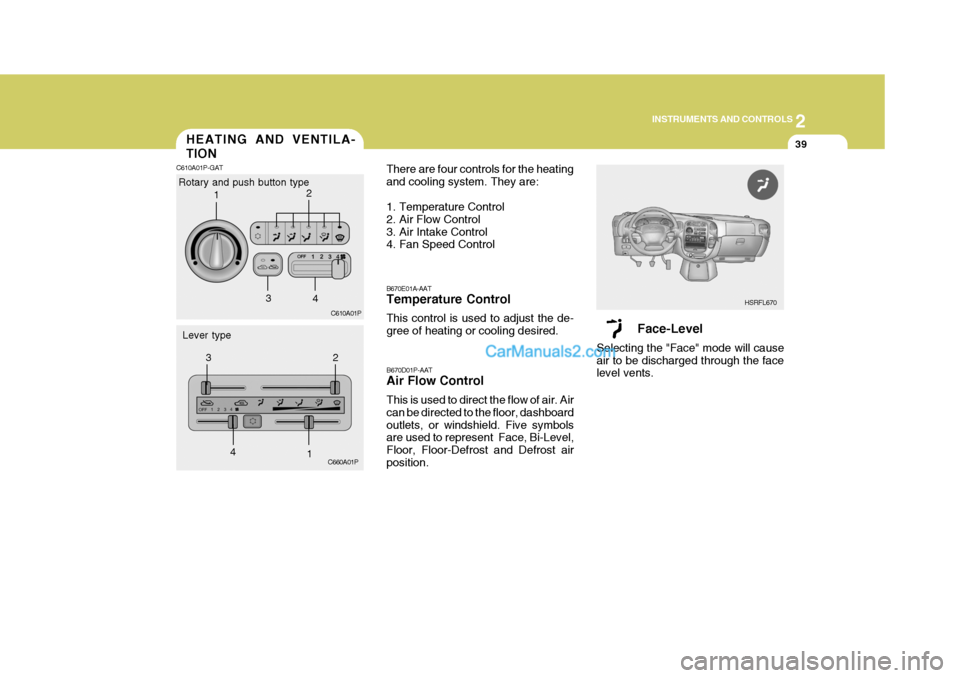
Rotary and push button type
Lever type C610A01P
C660A01P B670D01P-AAT Air Flow Control This is used to direct the flow of air. Air can be directed to the floor, dashboardoutlets, or windshield. Five symbols are used to represent Face, Bi-Level, Floor, Floor-Defrost and Defrost airposition.
B670E01A-AAT Temperature Control This control is used to adjust the de- gree of heating or cooling desired.
There are four controls for the heatingand cooling system. They are:
1. Temperature Control
2. Air Flow Control
3. Air Intake Control
4. Fan Speed Control
1
2
3 4
12
3
4
Page 110 of 284

2
INSTRUMENTS AND CONTROLS
41
B670B01A-AAT Fan Speed Control (Blower Control) This is used to turn the blower fan on or off and to select the fan speed.This blower fan speed, and therefore the volume of air delivered from the system, may be controlled manuallyby setting the blower control between the "1" and "4" positions.
Defrost-Level
Air is discharged through the wind-shield defroster nozzle and side venti- lator.If the "Defrost" mode is selected, the A/C will turn on automatically and "Fresh" mode will be activated to im-prove windshield defrosting. HSRFL674B670C01A-AAT Air Intake Control This is used to select fresh outside air or recirculation inside air.
Fresh Recirculation
With the mode selected, air enters the vehicle from outside and is heatedor cooled according to the other func- tions selected. With the mode selected, air fromwithin the passenger compartment is drawn through the heating system and heated or cooled according to the otherfunctions selected. NOTE: It should be noted that prolonged operation of the heating system in mode will give rise to misting
of the windshield and side win-dows and the air within the passen- ger compartment will become stale. In addition prolonged use of the airconditioning with the mode se- lected may result in the air within the passenger compartment becom-ing excessively dry.
Page 111 of 284

2 INSTRUMENTS AND CONTROLS
42VENTILATIONBI-LEVEL HEATINGHEATING CONTROLS
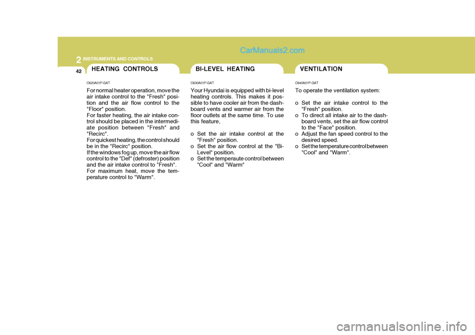
C620A01P-GAT For normal heater operation, move the air intake control to the "Fresh" posi- tion and the air flow control to the "Floor" position.For faster heating, the air intake con- trol should be placed in the intermedi- ate position between "Fresh" and"Recirc". For quickest heating, the control should be in the "Recirc" position.If the windows fog up, move the air flow control to the "Def" (defroster) position and the air intake control to "Fresh".For maximum heat, move the tem- perature control to "Warm". C630A01P-GAT Your Hyundai is equipped with bi-level heating controls. This makes it pos- sible to have cooler air from the dash- board vents and warmer air from thefloor outlets at the same time. To use this feature,
o Set the air intake control at the
"Fresh" position.
o Set the air flow control at the "Bi- Level" position.
o Set the temperaute control between
"Cool" and "Warm" C640A01P-GAT To operate the ventilation system:
o Set the air intake control to the
"Fresh" position.
o To direct all intake air to the dash- board vents, set the air flow control to the "Face" position.
o Adjust the fan speed control to the desired speed.
o Set the temperature control between "Cool" and "Warm".
Page 112 of 284

2
INSTRUMENTS AND CONTROLS
43
To use the heating/ventilation system to defrost or defog the windshield:
o Set the air flow control (3) to the
"Def" position. (If the "DEF" mode is selected, the A/C will turn on auto- matically and "Fresh" mode will be activated.)
o Set the temperature control (1) to a comfortably warm position.
o Set the fan speed control (5) to position 3 or 4.
NOTE: In high humidity areas, the A/C can be used with the air intake in the"Recirc" position for increased de- fogging action. C670A01P-GAT Operation Tips
o To keep dust or unpleasant fumes
from entering the vehicle through the ventilation system, temporarily set the air intake control at "Recirc". Be sure to return the control to"Fresh" when the irritation has passed to keep fresh air in the ve- hicle.This will help keep the driver alert and comfortable.
o Air for the heating/cooling system is drawn in through the grilles justahead of the windshield. Care should be taken that these are not blockedby leaves, snow, ice or other ob- structions.
o To prevent interior fog on the wind- shield, set the air intake control tothe fresh air (
) position, fan speed
to the desired position, turn on the air conditioning system, and adjust tem- perature control to desired tempera- ture.
DEFROSTING/DEFOGGING
C660A02P-GAT
C660B01P
C660A01P
Rotary and push button type
Lever type 1
23
4
5
12
3
4 5