Page 269 of 484

SR-13Steering System�Power Steering (On-Vehicle Inspection)
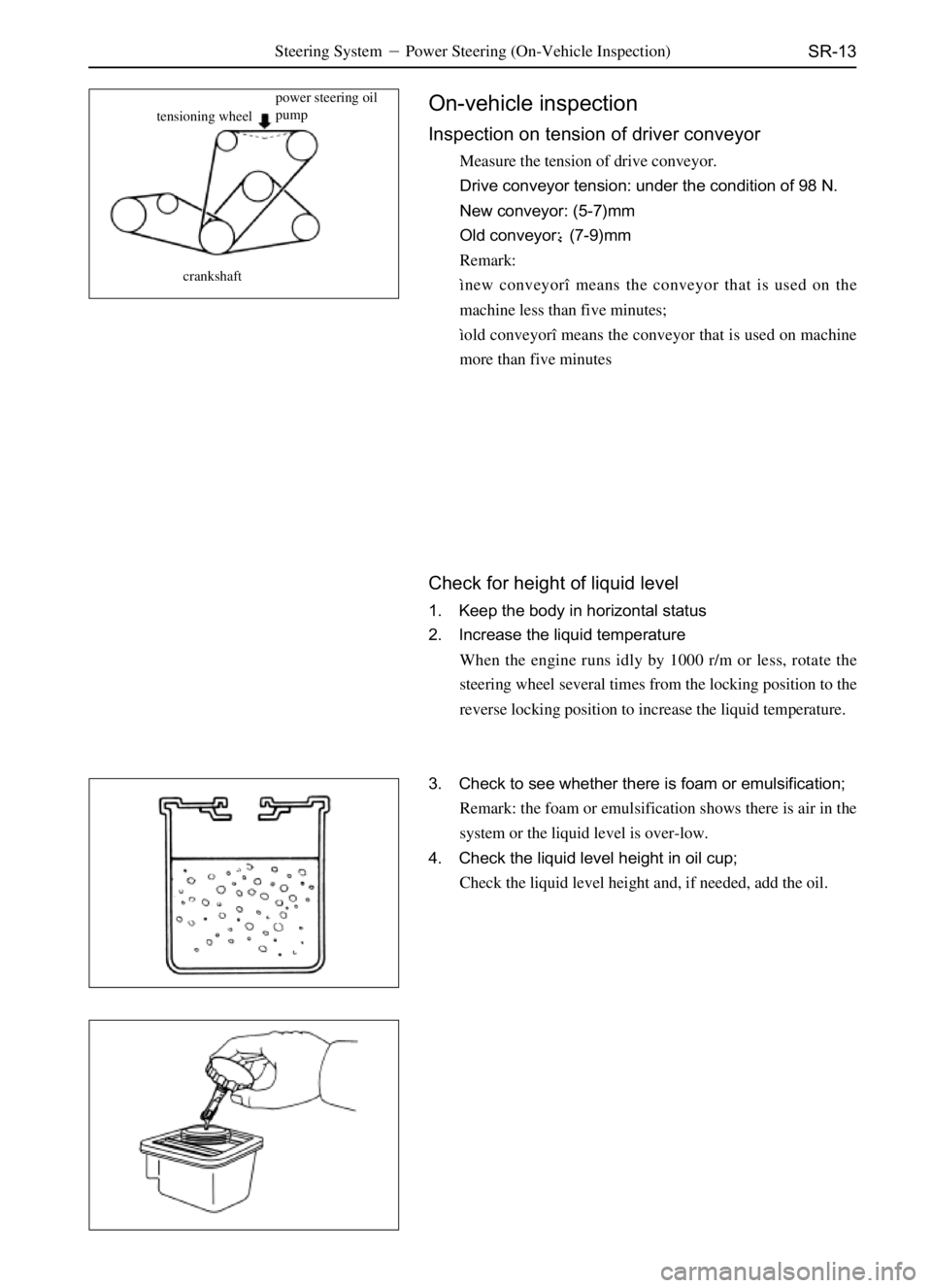
tensioning wheelpower steering oil
pump
crankshaftOn-vehicle inspection
Inspection on tension of driver conveyor
Measure the tension of drive conveyor.
Drive conveyor tension: under the condition of 98 N.
New conveyor: (5-7)mm
Old conveyor:�(7-9)mm
Remark:
ìnew conveyorî means the conveyor that is used on the
machine less than five minutes;
ìold conveyorî means the conveyor that is used on machine
more than five minutes
Check for height of liquid level
1. Keep the body in horizontal status
2. Increase the liquid temperature
When the engine runs idly by 1000 r/m or less, rotate the
steering wheel several times from the locking position to the
reverse locking position to increase the liquid temperature.
3. Check to see whether there is foam or emulsification;
Remark: the foam or emulsification shows there is air in the
system or the liquid level is over-low.
4. Check the liquid level height in oil cup;
Check the liquid level height and, if needed, add the oil.
Page 270 of 484

SR-14Steering System�Power Steering (On-Vehicle Inspection)
Change of power steering liquid
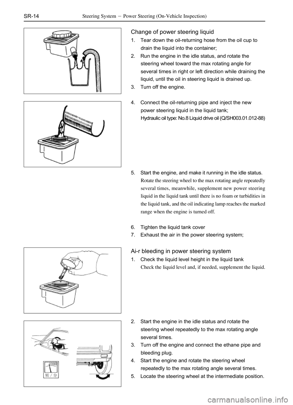
1. Tear down the oil-returning hose from the oil cup to
drain the liquid into the container;
2. Run the engine in the idle status, and rotate the
steering wheel toward the max rotating angle for
several times in right or left direction while draining the
liquid, until the oil in steering liquid is drained up.
3. Turn off the engine.
4. Connect the oil-returning pipe and inject the new
power steering liquid in the liquid tank;
Hydraulic oil type: No.8 Liquid drive oil (Q/SH003.01.012-88)
5. Start the engine, and make it running in the idle status.
Rotate the steering wheel to the max rotating angle repeatedly
several times, meanwhile, supplement new power steering
liquid in the liquid tank until there is no foam or turbidities in
the liquid tank, and the oil indicating lamp reaches the marked
range when the engine is turned off.
6. Tighten the liquid tank cover
7. Exhaust the air in the power steering system;
Ai-r bleeding in power steering system
1. Check the liquid level height in the liquid tank
Check the liquid level and, if needed, supplement the liquid.
2. Start the engine in the idle status and rotate the
steering wheel repeatedly to the max rotating angle
several times.
3. Turn off the engine and connect the ethane pipe and
bleeding plug.
4. Start the engine and rotate the steering wheel
repeatedly to the max rotating angle several times.
5. Locate the steering wheel at the intermediate position.
Page 271 of 484
SR-15Steering System�Power Steering (On-Vehicle Inspection)
6. Exhaust the air in steering system:
(a) Loosen the bleeding plug;
(b) Screw up the bleeding plug when there is no air bubble
exhausted from the pipeline.
Notice: take care not let the ethane pipe slide from the
bleeding plug, because the liquid is high in temperature
and pressure.
7. Check to see whether there is air bubble or turbidities
in the oil cup, and ensure the liquid level will not
exceed the max value when the engine stops,
Measure the liquid height under the condition of engine running,
then turn off the engine and measure the liquid height again.
In case any problem is found, repeat the approaches of (5) and
(6) in Power Steering Liquid Change. If the problem still
exists, repair the power steering oil pump.
RPM RPM
Page 280 of 484

BE-2
Brief Introduction
1. Power supply system
The power supply system includes accumulator, generator and its adjustor. Generator is the main power supply; the
accumulator is the auxiliary power supply. The generator, parallel with the accumulator, is equipped with the
adjustor, which is used to maintain the voltage of generator stable when the rotating velocity and the load varies.
2. Starting System
Which includes the direct current motor, drive mechanism and control device, etc. its performance is to start the
engine.
3. Lighting system
Which includes various lighting lamps inside and outside of the body and their control device; they are used mainly
to guarantee safety driving in night.
4. Alarming System
Which includes the electric horn, flasher and various service signal indicating lamps, etc. they are mainly used to
guarantee the physical and driving safe when driving.
5. Auxiliary Electric Appliance System
It includes the electric wiper, air-conditioner, recorder and cigarette lighter, etc.
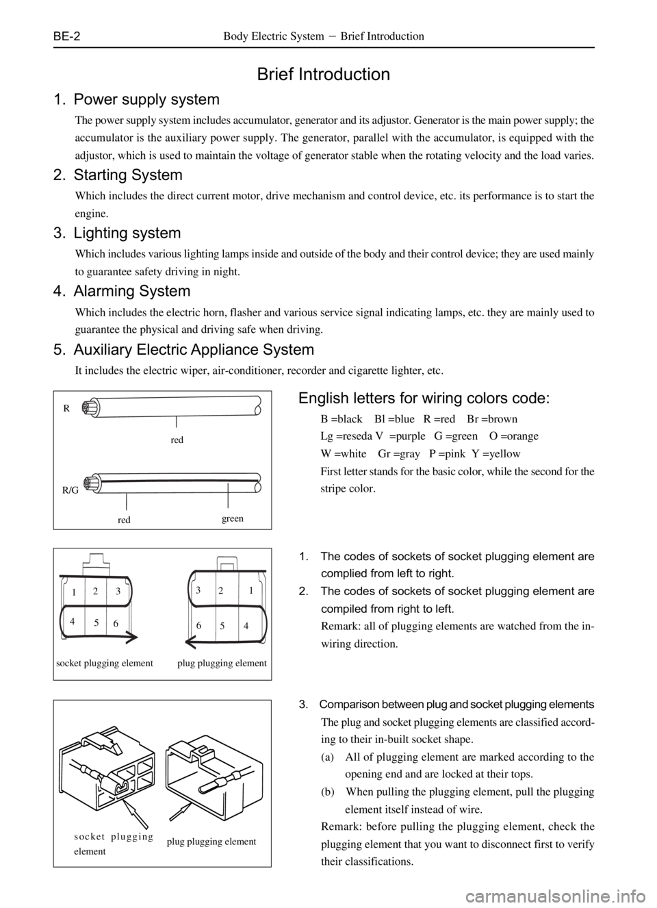
R
red
R/G
redgreen
socket plugging element plug plugging elementN
2 3
4 5 6 123
4
5
S
socket plugging
elementplug plugging element
1. The codes of sockets of socket plugging element are
complied from left to right.
2. The codes of sockets of socket plugging element are
compiled from right to left.
Remark: all of plugging elements are watched from the in-
wiring direction.
3. Comparison between plug and socket plugging elements
The plug and socket plugging elements are classified accord-
ing to their in-built socket shape.
(a) All of plugging element are marked according to the
opening end and are locked at their tops.
(b) When pulling the plugging element, pull the plugging
element itself instead of wire.
Remark: before pulling the plugging element, check the
plugging element that you want to disconnect first to verify
their classifications.
English letters for wiring colors code:
B =black Bl =blue R =red Br =brown
Lg =reseda V =purple G =green O =orange
W =white Gr =gray P =pink Y =yellow
First letter stands for the basic color, while the second for the
stripe color.
Body Electric System�Brief Introduction
Page 342 of 484
BE-64
Inspection on Common Trouble
k
v
kk
v
ON
OFF
blue screen
black screen
(a) Main engine cannot be opened
Ther is no action when pressing
the �ower�key repeatedlyCheck whether the voltage of
ACC and storage cell reaches
12 VCheck the fuse in power wire
or the power supply of the
entire vehicle
Failure of main
engine
(b) No voice or image when broadcasting
�NO CDC�displayed on
screenRe-open the deviceCheck whether there is image
when backing upFailure of main
engine
Be normal after
returning
Check the converter box works
normally (whether the lamp is
light or not)Failure of converter
box
Failure of disc box
(c) There is no image when backing up
There is no image in
video cameraWhether the screen display
is blue screenFailure of video
camera
The backing up wire is not connected
well; reconnect it to the positive polar
of 12V of reverse gear
Body Electric System�Acoustical Equipment System
Page 374 of 484

AC-11Air-Conditioning System�Inspection On Refrigerant Quantity
Inspection on Refrigerant Quantity
1. Run the engine at the speed of 1500 r/m or so (the
atmospheric temperature should be above 35�);
2. Start the air-conditioner in the max cold air status for
several minutes;
3. Check the refrigerant quantity.
Watch the observation window on liquid tank.
Dr SF
SL SK SY SJ
liquid tank
liquid tankobservation window
observation window
No.
1
2
3
4
5
6
Symptoms
Refrigerant quantityRepairing approaches
Air bubble occurs in the observa-
tion window
No air bubble in observation win-
dow
No temperature difference between
the inlet and outlet of compressor
Obvious temperature difference be-
tween the inlet and outlet of compressor.
Observation window is in clear status
once the air-conditioner is turned off
There is refrigerant foam on observa-
tion window after the air-conditioner
is turned off, then the observation
window becomes clear.Insufficient
No, normal or redundant
No, or almost no
Normal or redundant
Redundant
NormalCheck to see whether there is leakage with the
gas leakage detector
Refers 3 and 4.
Vacuumize the system and inflate the
refrigerant, then check to see whether there is
leakage with the gas leakage detector.
Refer 5 and 6
Exhaust the redundant refrigerant until the speci-
fied quantity is satisfied.
Page 375 of 484

AC-12Air-Conditioning System�Compressor
Installation of manifold gauge
Remark: Connect the manifold gauge to the auxiliary valve of
compressor.
1. Turn off the manual valve of manifold gauge.
2. Mount the packing hose of manifold gauge on the packing
valve.
Mount the LP hose to the LP packing valve and the HP hose to
HP packing valve. Then screw up the nuts for hose joint by
hand.
Remark: Do not coat the compressor lubricant on the connec-
tion positions.
packing hose
efrigeration system
connected to mani-
fold gauge
connect to compressor
turn offturn offCompressor
On vehicle inspection
1. Mount the manifold gauge;
(see manifold gauge mount)
2. Run the engine at the speed of 1500 r/m or so;
3. Check the compressor according to the following items:
(a) The HP gauge readings under the normal system should
satisfy the specified value of (1.4-1.7)MPa , that of LP
gauge should meet the specified value of (0.15-0.2)MPa .
(b) Whether there is abnormal sound;
(c) Whether there is leakage at the shaft oil seal.
If any problem is found, repair or change the compressor.
4. Check the electromagnetic clutch:
(a) Check to see whether there is lubricant trace on the
pressing plate and rotor;
(b) Check to see whether there is noise or lubricant leakage
at the clutch bearing;
(c) Measure the resistance between the stator coils that is set
between the clutch lead and the grounding lead with the
ohmn meter.
Standard resistance:
SL SK SJ�(3.2�.2)
Ω
Dr SF SY�(3.5�.2)Ω
In case the requirement is not satisfied, change the compressor.
Page 379 of 484

AC-16Air-Conditioning System�Refrigeration Device
Refrigeration device
On-vehicle inspection on expansion valve
1. Check the gaseous refrigerant quantity in the refrigeration
cycle;
2. Mount the manifold gauge;
(see Page AC-12)
3. Run the engine;
Run the engine at a speed of 2000 r/m for five minutes.
4. Check the expansion valve;
If the expansion valve is blocked, the LP readings will reduce
to 0 kPa, otherwise, the valve is normal.
Disassembly of Refrigeration Device
1. Disconnect the cathode lead from the storage cell;
2. Exhaust the refrigerant;
3. Tear down the suction pipe from the entrance joint of
refrigeration device;
4. Tear down the outlet pipe from the entrance joint of
refrigeration device;
Remark: the opened joint should be sealed with the cork to
prevent the humid air from entering into the system.
5. Tear down the insulation rings from the inlet and outlet
joints.
6. Tear down the right glove box (SY rear air-conditioner:
tear down the interior trim panel at left rear side).
7. Disconnect the plugging element;
8. Tear down the refrigeration device;
Tear down the three nuts.
refrigeration device
SYinterior trim panel
at left rear side
rear evaporator