Page 5 of 484
IN-1
Page
How to use this manual ................................................. IN-2
Instruction for overall repairing ...................................... IN-4
Body lifting height and support position ........................ IN-5
fk
Introduction
Page 9 of 484

IN-5
Body lifting height and supporting position
wrong correct
Introduction�Body Lifting Height and Supporting Position
Jack lifting position
...........................................................................................................
Front......the front the beam center
Rear.....rear differential
Supporting position
�safety bracket .............................................................................................
front
123456
123456
123456
123456
123456
12345
12345
12345
12345
b) The raised vehicle must be supported with the bracket; it is
dangerous to conduct the repairing work on the vehicle propped
up with one jack, even though such repairing can be finished in
short time.
12. The following items shall be taken notice to avoid the parts damage:
a) Do not open the covers of ECU and various computers where not
necessary absolutely. (if the IC terminal is touched, it be leaded
into static damage) .
b) Pull the hose at its ends when dismantling it, do not pull it at the
center section.
c) Pull the wire joint instead of the wire when pulling the joint
away.
d) Take notice to avoid of the drop of electric parts such as the
sensors or repeaters. In case those parts drop to the hard ground,
they must be changed instead of being reused.
e) Do not use the striking spanner to dismantle or mount the
thermostatic switch or thermostatic sensor.
f) Plug the needles of the multi-meter into the wire connector
carefully when checking its conductance and do not bend the
terminals.
g) Do not sheath the hose of the vacuum gauge into the very large
connector when using the gauge, instead, the stage joint shall be
used because once the hose expands, it is possible to lead into
the leakage.
Page 12 of 484

CL-3Clutch�Inspection and Adjustment of Clutch Pedal, Air Exhausting of Clutch
Air-exhausting of clutch
Remark: in case operation needs to be conducted for the clutch
system or if there is air in clutch, exhaust the air.
Notice : Do not stain the painted surface with brake liquid,
if any brake liquid is left, wash it away immediately.
1.
Fill the brake liquid into the oil cup of clutch master cylinder;
The oil cup of master cylinder shall often be checked and, if
necessary, added with brake liquid.
2.
Connect the ethene resin pipe to the air-exhausting valve.
Insert the other end of the pipe into the container, half of which
is filled with brake liquid.
3. Air-exhausting in clutch system
a) Move the clutch pedal up and down slowly for several times.
b) Loosen the air-exhausting valve when pressing the pedal
increasingly until there is brake liquid overflowing, then
tighten the air-exhausting valve.
c)
Repeat this operation until the bubble in brake liquid disappears.
Inspection on and adjustment
of clutch pedal
1. Check whether the pedal height is correct
Pedal height that begins from front wall board:
Dr SF�(165�5)mm
SL SK SY SJ�(190-200)mm
2. Adjust the pedal height where necessary
Loosen the locking nut and screw off the adjusting bolts until
the pedal height is correct. Then screw up the locking nut.
Pedal free stroke
3. Check whether the pedal free stroke is correct
Press the pedal lightly until the resistance generated by clutch
occurs.
pedal free stroke: (5-15)mm
4. Adjust the pedal free stroke where necessary;
a) Loosen the locking nut and rotate the push-rod until the
stroke is correct;
b) Screw up the locking nuts;
c) Check the pedal height after the adjustment of pedal free
stroke.
adjusting spot in
pedal height
pedal height
pedal free stroke
Page 106 of 484
PR-8Drive Shaft�Drive Shaft
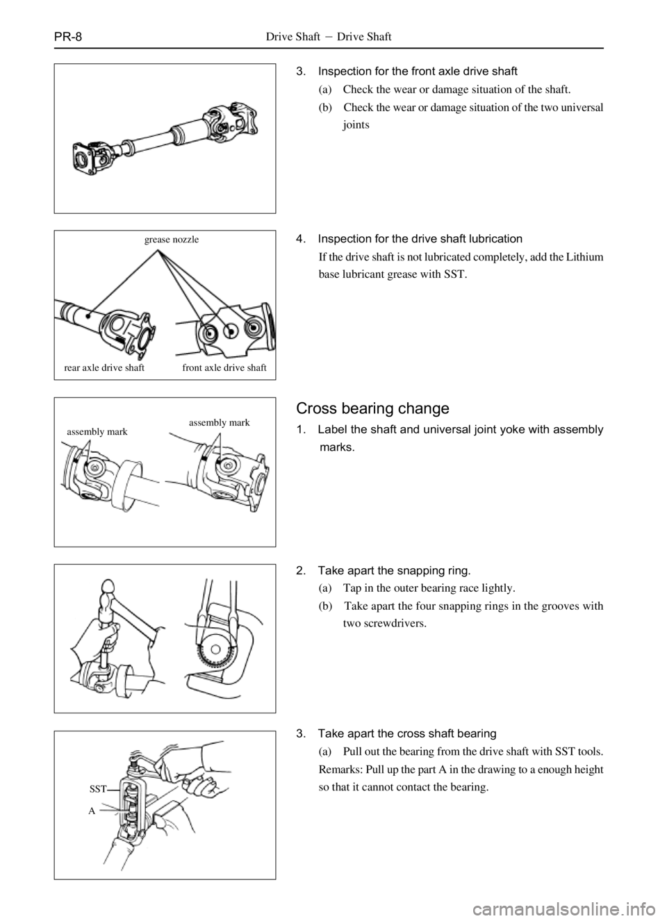
3. Inspection for the front axle drive shaft
(a) Check the wear or damage situation of the shaft.
(b) Check the wear or damage situation of the two universal
joints
grease nozzle
rear axle drive shaft front axle drive shaft
assembly mark
assembly mark
SST
A4. Inspection for the drive shaft lubrication
If the drive shaft is not lubricated completely, add the Lithium
base lubricant grease with SST.
Cross bearing change
1. Label the shaft and universal joint yoke with assembly
marks.
2. Take apart the snapping ring.
(a) Tap in the outer bearing race lightly.
(b) Take apart the four snapping rings in the grooves with
two screwdrivers.
3. Take apart the cross shaft bearing
(a) Pull out the bearing from the drive shaft with SST tools.
Remarks: Pull up the part A in the drawing to a enough height
so that it cannot contact the bearing.
Page 116 of 484

SA-5
7. Check the sliding measuring situation.
Check the sliding situation with the sliding measuring tester.
Sliding measuring value: �.5m/km
push forward the vehicle;
forward
A=BB A
6. Wheel toe-in adjustment
(a) Verify that each wheel has been located forward in a line.
(b) Mark the tire center at the bearing height on the tread of
left and right tire, and measure the distance between the
marks on left and right treads.
(c) Push forward the vehicle until the mark on the back tread
of tire moves to the front.
Remark: the toe-in measurement should be conducted from the
same spot at the same height.
(d) Measure the distance between the two marks on the front
of two treads.
Toe-in value: (0-2)mm
(e) Loosen the clamping bolts of connecting pipe.
(f) Adjust the toe-in angle through the approach according to
which rotate the left and right drag rod tube by a same
angle.
Remark: check the lengths of the two drag rods to see whether
the two rods are same in length.
Length error of the left and right drag rod should not
be larger than 2.0mm.
(g) Tighten the clamping bolts.
Fastening torque�(20�) N�m
(h) Locate the split pin well.
Suspension System and Automobile Axle�Alignment of Front Wheel (Dr SL SK SY SJ)
Page 117 of 484

Alignment of Front Wheel
(SF)
1. The following items should be checked to remove the
troubles.
(a) Chec")
SA-6Suspension System and Automobile Axle�Alignment of Front Wheel�Alignment of Front Wheel (SF)
Alignment of Front Wheel
(SF)
1. The following items should be checked to remove the
troubles.
(a) Check the tire abrasion and the air inflation to see it is
suitable or not.
Tire inflation pressure: (250�0)kPa
(b) Check the front wheel bearing to see whether it is loose.
(c) Check the front suspension to see whether it is loose.
(d) Check the steering driving device to see whether it is
loose, and
(e) Check the front vibration through elastic force test to see
whether it is normal in performance.
2. Height adjustment of vehicle
Adjust the vehicle height to the standard value so as to make
the Alignment of Front Wheel inspection.
A-B-58 5mm
A: The height of steering knuckle shaft center.
B: The center height of the adjusting cam bolt at front end
The standard value for the unloaded height is: the
difference of the center height of drive shaft climax and
the front adjusting cam bolt is 58.5mm.
3. Mount on the four wheel locating device
This approach should be conducted according to the detailed
instruction of the equipment manufacturer.
4. Adjust the outer tilt angle of front wheel and the back tilt
angle of kingpin
The outer tilt angle of front wheel: 0�5'�0'
The back tilt angle of kingpin: 2�0'�0'
Outer inclination of front wheel:
BA
the outer tilt angle of
front wheelthe back tilt angle
of kingpin
front
Page 119 of 484
SA-8Suspension System and Automobile Axle�Alignment of Front Wheel (SF)
(c) Mark the center of the back of front wheel, and measure
the distance ìBî between the remarks on the left and right
tires.
(d) Push the vehicle forward so that the mark on the back of
tire moves to the measuring height of the instrument.
Remark: if the tire moves too far, repeat the approach (b).
(e) Measure the distance ìAî between the marks on the front
of tire.
(f) Measure the wheel toe-in.
Toe-in = B-A
Inspection standard: (0-2)mm
In case the toe-in fails to conform to the specified value, it can
be amended through adjusting the left and right drag rods.
(g) Loosen the clamping bolt and nut.
(h) Adjust the toe-in situation by the approach of rotating the
left and right drag rod by a same angle.
(i) Ensure the left and the right drag rods are same in length.
B
forward
move the vehicle forward
A
front
A
B
A=B
Page 143 of 484
SA-32
(h) Bend one tooth of the lock plate inside and other teeth
outside to lock the steering knuckle nut.
5. Mount on the liner and the steering knuckle outer flange
cap.
Fastening torque�(23-29)N�m
6. Mount the brake caliper
(a) Mount the brake caliper on the steering knuckle and
screw up the bolts according to the specified torque.
Fastening torque�123N�m
(b) Connect the Bundy tube.
Fastening torque�(20-22)N�m
7. Check the height of the brake liquid level and add the
brake liquid as requirement, exhaust the gas in the
braking system.
Steering knuckle
Dismantle of Steering Knuckle
1. Tear down the brake caliper, front wheel and the front
brake disc.
2. Tear down the dust cover, and the brake shell.
3. Tear down the steering knuckle arm from the steering
knuckle.
Suspension System and Automobile Axle (SF/2WD) �Front Wheel Hub and Steering Knuckle (Steering Knuckle)