Page 234 of 484

BR-23
Wheel-brake cylinder disassembly:
1. Tear down the dust cover steel gripping hoop and the
dust cover.
Tear down the dust cover steel gripping hoops and piston dust
covers of the four wheel-brake cylinders with the screwdriver.
2. Tear down the piston from the wheel-brake cylinder:
(a) Prepare a wooden block with the dimensions as shown in
the drawing (which is used to support the piston)
(b) Put the wooden block between the pistons and insert one
brake pad on one side of the wooden block.
(c) Tear down the four pistons from the wheel-brake cylin-
der by using the compressed air.
Warning: do not put your fingers in front of the piston
when using the compressed air.
3. Tear down the piston sealing ring.
Tear down the four piston sealing ring from the wheel-brake
cylinder with the screwdriver.
Check the front brake parts
1. Measure the thickness of brake pad liner;
Standard thickness�9.0mm
Min thickness�2.0mm
In case the liner is less than the min thickness or the liner is
worn unevenly, change the brake pad. Braking System�Front Brake(SF)
mm
mm
mm
Page 235 of 484

BR-24
2. Measure the thickness of brake disc;
Standard thickness�20.0mm
Min thickness�18.0mm
If the brake pad is scraped, repair it; where the abrasion is
serious and its thickness is smaller than the min thickness,
change the brake disc.
3. Measure the bounding value of the brake disc face;
Remark: the bearing is required to be verified in the suitable
adjustment before measuring.
Max face bouncing value: 0.11mm;
4. Change the brake disc according to the requirement:
(a) Tear down the hub and the brake disc. (see the paragraph
of front wheel hub)
(b) Mount the new brake disc and screw up the connecting
bolts as the specified torque.
(c) Mount the hub and brake disc assembly. (see the para-
graph of front wheel hub).
Fastening torque�(75�5)N�m
(d) Mount the caliper bracket on the steering knuckle and
screw up the bolts according to the specified torque.
Fastening torque�123N�m.
Assembly of Brake-wheel pump
1. Preparation
All parts shall be washed, dried and cleared away the alien
materials, and coat moderate rubber lubricant on the work
faces of piston, piston dust cover and rectangular sealing ring.
2. Encase the piston sealing ring in the caliper body Braking System�Front Brake(SF)
Page 237 of 484

BR-26
Rear brake
Element figure
wheel-brake cylinder cluster
pressure spring drag rod
self clearance-
adjusting bracing
wireparking brake arm
flat washer�split pinbrake shoe gear
return spring
parking brake push plate
push-plate spring back brake
shoe
self clearance-
adjusting toggle
tension spring
brake drum
clearance adjuster
pressure spring seatpressure spring front brake shoe
Disassembly of Rear drum-type Brake
Remark: if the braking torque of manual brake cannot satisfies
the braking requirement, it is suggested to check the thickness
of brake shoe liner, where the thickness is less than the min
thickness, change the brake shoe.
Min thickness�1.0mm
1. Tear down the rear wheel;
2. Tear down the brake drum;
Remark: in case the brake drum is not easy to tear down, the
following steps shall be adapted:
(a) Tear down the clearance-adjusting hole; insert a screw-
driver in the brake bottom plate hole to prize up the
adjusting bolt inner tilt angle with the self-adjusting fork.
(b) Use another screwdriver to adjust the adjusting bolt inner
tilt angle to loosen the clearance adjuster of brake shoe. DrBraking System�Rear Brake (Dr)
�Parts that cannot be reused after being used
Page 245 of 484

BR-34
Rear brake
Element figure
�Parts that cannot be reused after using.wheel-brake cylinder cluster
observation hole cork�
claming pin
observation hole cork�
front brake shoe
pressure spring caplower tension springupper tension spring clearance adjuster
rear brake shoe
brake lever
toggle plate
�open retainer ring
clearance-adjusting spring
brake drum pressure spring
Disassembly of Rear Brake
1. Check the thickness of the brake shoe liner:
Tear down the observation hole cork I and measure the thickness
of brake shoe liner through the observation hole. If the thickness
if less than the min thickness, change the brake shoe.
Min thickness�1.0mm
2. Tear down the rear wheel.
3. Tear down the brake drum;
Remark: if the brake cannot be tear down easily, the following
steps shall be adapted:
(a) Tear down the observation hole cork II by inserting the
screwdriver in the hole of brake bottom plate, and poke
the toggle plate from the self-adjusting screw arbor.
(b) Loosen the brake shoe clearance adjuster with another
screwdriver by screwing the self-adjusting screw arbor. SF
Braking System�Rear Brake (SF)
Page 258 of 484

SR-2
Notice
The parts change should be conducted correctly because
any error will affect the properties of steering system, or lead
to accidental or damage when driving.
Troubleshooting
Trouble Causes Inspection items
Unsuitable tire inflation
Insufficient lubricant
Over-large inclination
Steering gear joint wear
Lower swing arm ball head wear
Steering column seize-up
Steering gear unsuitable adjustment or damage
Power steering conveyer looseness
Over-low liquid level in oil cup of steering pump
Failure in power steering mechanismInflate the tire to specified pressure
Lubricating the hanging devices
Check the Alignment of Front Wheel
Change the Steering gear joint
Change the lower swing arm ball
head;
Check the steering column
Adjust or repair the gear.
Adjust the conveyor.
Check the steering pump oil cup
Check the power steering devices
Poor returning
Unsuitable tire inflation
Insufficient lubricant
Incorrect wheel alignment
Steering column seize-up
Steering gear unsuitable adjustment or damageInflate the tire to specified pressure
Lubricating the hanging devices.
Check the Alignment of Front
Wheel
Check the steering column
Change the steering gear.
Over-large playFront wheel bearing wear
Steering drive shaft yoke wear
Lower swing arm ball head wear
Steering gear joint wear
Steering gear unsuitable adjustment or damageChange the front bearing
Change the steering drive shaft
Change the swing arm ball head
Change the steering gear joint
Change the steering joint
Abnormal noise
Steering drive lever looseness
Steering gear joint wear
Steering gear unsuitable adjustment or damage
Oil lack or poor sealing of steering machine.Tighten the steering drive lever
Change the steering gear joint
Change the steering gear
Add the oil or change the sealing
washer Steering system inspection
on vehicle.
Steering System�Notice and Troubleshooting
Difficulty in steering
Page 270 of 484

Change of power steering liquid
1. Tear down the oil-returning hose from the oil cup to
drain the liquid into the container;
2. Run the engi")
SR-14Steering System�Power Steering (On-Vehicle Inspection)
Change of power steering liquid
1. Tear down the oil-returning hose from the oil cup to
drain the liquid into the container;
2. Run the engine in the idle status, and rotate the
steering wheel toward the max rotating angle for
several times in right or left direction while draining the
liquid, until the oil in steering liquid is drained up.
3. Turn off the engine.
4. Connect the oil-returning pipe and inject the new
power steering liquid in the liquid tank;
Hydraulic oil type: No.8 Liquid drive oil (Q/SH003.01.012-88)
5. Start the engine, and make it running in the idle status.
Rotate the steering wheel to the max rotating angle repeatedly
several times, meanwhile, supplement new power steering
liquid in the liquid tank until there is no foam or turbidities in
the liquid tank, and the oil indicating lamp reaches the marked
range when the engine is turned off.
6. Tighten the liquid tank cover
7. Exhaust the air in the power steering system;
Ai-r bleeding in power steering system
1. Check the liquid level height in the liquid tank
Check the liquid level and, if needed, supplement the liquid.
2. Start the engine in the idle status and rotate the
steering wheel repeatedly to the max rotating angle
several times.
3. Turn off the engine and connect the ethane pipe and
bleeding plug.
4. Start the engine and rotate the steering wheel
repeatedly to the max rotating angle several times.
5. Locate the steering wheel at the intermediate position.
Page 313 of 484

BE-35Body Electric System�Combination Instrument
Common Troubleshooting
a. Such failures as inaccuracy indication, out-operation of indicator, on the fly of large and small summation meters
(mechanical wheel drive excluded) or incomplete liquid crystal display are caused by the interior failures of the
instrument, therefore, these failures, once occur, should be judged according to the instrument interior failures, and
change the combination instrument directly.
b. In case both the large and small summation meter and the indicator of electronic odometer are on the fly, such failures
can be removed by disassembling the speed sensor from the whole vehicle first, then connecting the sensor and
combination instruments as shown in the drawing.
Then, open the power supply and run the rotors quickly to observe the indicator variation of odometer.
the odometer indicator
should be no less than 40Km/
h variation in speed under
common condition whenrunning the rotors,
otherwise,
change with the good sensor
good combination instruments
vÉë
No
Yes
No
Yes
No
installation of sensorconnector for wiring harnessmalfunction of sensorfailure of instrument
panel connector for wiring
harness
��12V�
combination instrument
�
�
signal input
sensor
Page 407 of 484
B0-24
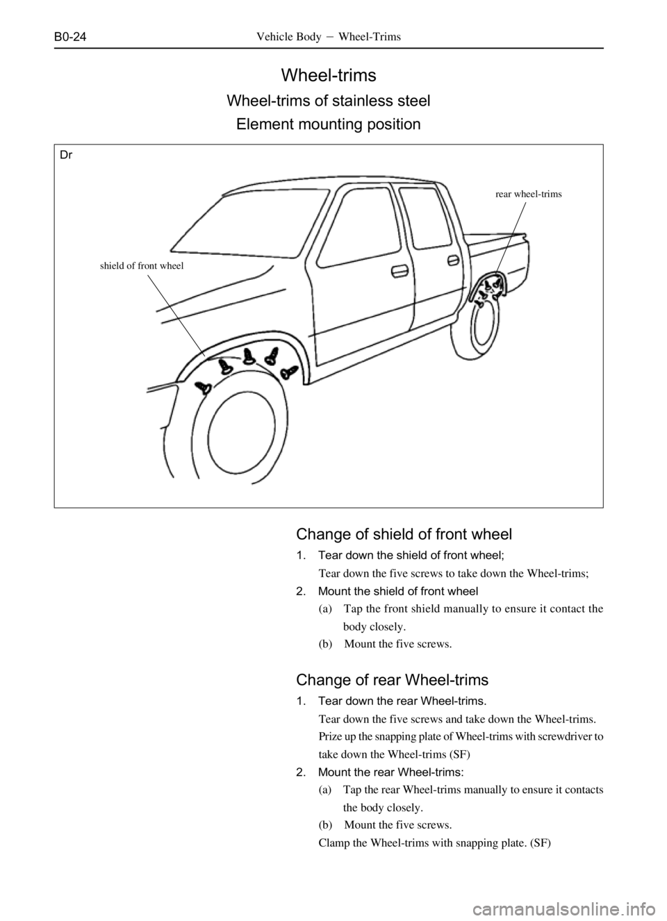
Wheel-trims
Wheel-trims of stainless steel
Element mounting position
Vehicle Body�Wheel-Trims
Change of shield of front wheel
1. Tear down the shield of front wheel;
Tear down the five screws to take down the Wheel-trims;
2. Mount the shield of front wheel
(a) Tap the front shield manually to ensure it contact the
body closely.
(b) Mount the five screws.
shield of front wheel
rear wheel-trims
Dr
Change of rear Wheel-trims
1. Tear down the rear Wheel-trims.
Tear down the five screws and take down the Wheel-trims.
Prize up the snapping plate of Wheel-trims with screwdriver to
take down the Wheel-trims (SF)
2. Mount the rear Wheel-trims:
(a) Tap the rear Wheel-trims manually to ensure it contacts
the body closely.
(b) Mount the five screws.
Clamp the Wheel-trims with snapping plate. (SF)