Page 425 of 484

B0-42Vehicle Body�Rear Windshield
Mount of rear windshield
1. Clean the body and glass;
Clean the contacting face of body and glass with the
cleaning materials.
2. Clean the sealing strip
Clean the sealing strip with cleaning materials;
4. Mount the rear windshield
(a) Lay the ready glass against the corresponding position of
rear windshield opens.
(b) Pull the rope from the inside of body to encase the roof,
the rear column and the door frame within the adhesive
strip, meanwhile push the outside of the glass by hand.
(c) Tap the four edges of the adhesive strip to ensure that the
adhesive strip contact closely with the body windshield
opened.
(d) Coat the glue from left to right at the upper part of
windshield (location between the adhesive strip and the
body windshield open) and the lower part of windshield
(location between the adhesive strip and glass), and the
remaining glue should be cleared away with abrasive
paper, and the location should be cleaned with cloth.
Notice: there should no breakage at the sealing glue
seam when coating the glue.
Recommended sealing agent for use
Glass glue XL-1211 acid silicone glass glue
5. Check whether there is leakage and the leakage
reparation;
(a) Conduct the leakage test;
(b) Seal the leaking parts with glass glue. 3. Mount the rear windshield in the sealing strip
(a) Coat a layer of silicon oil around the glass circumference
and mount the adhesive strip on the glass according to
the glass shape.
Notice: if the adhesive strip becomes stiffening or
deforming that will lead to water leakage, change with
the new one where possibly.
(b) Mount a rope alongside the sealing strip channel as
shown in the drawing (fix the rope in the adhesive strip).
Page 450 of 484

Element figure
buffer blockspringy welt
trim cover of fixed bracket
decorative cover of screw hole reserve tire bracket
nut
SF
Dismantl")
B0-67Vehicle Body�Reserve Tire Bracket
Reserve tire bracket (�)
Element figure
buffer blockspringy welt
trim cover of fixed bracket
decorative cover of screw hole reserve tire bracket
nut
SF
Dismantle of reserve tire bracket
1. Tear down the trim cover of fixed bracket;
Tear down the decorative cover of screw hole, and then tear down the
trim cover of fixed bracket.
Tear down the adjusting arm (SY SJ)
Tear down the two bolts to take down the adjusting arm;
2. Tear down the reserve tire bracket;
Tear down the three bolts and take down the reserve tire bracket. (SF)
Tear down the three bolts and take down the reserve tire bracket. (SY
SJ)
Mount of reserve tire bracket
1. Mount the reserve tire bracket;
(a) Stick the springy welt on the corresponding face where the
reserve tire bracket contact with the body; (SF)
(b) Fix the reserve tire bracket on the body with eight bolts (SF).
Fix the reserve tire bracket with three bolts on the right mail sill
and tail beam of the body.
2. Mount the trim cover of fixed bracket;
Mount the trim cover of fixed bracket and the decorative cover of
screw hole.
Mount the adjusting arm (SY SJ)
Fix the adjusting arm on the tail beam bracket of the body by screwing
the two bolts in the fixing hole.
Notice: the paint layer should be well protected during
disassembling and assembling.
Page 456 of 484
B0-73
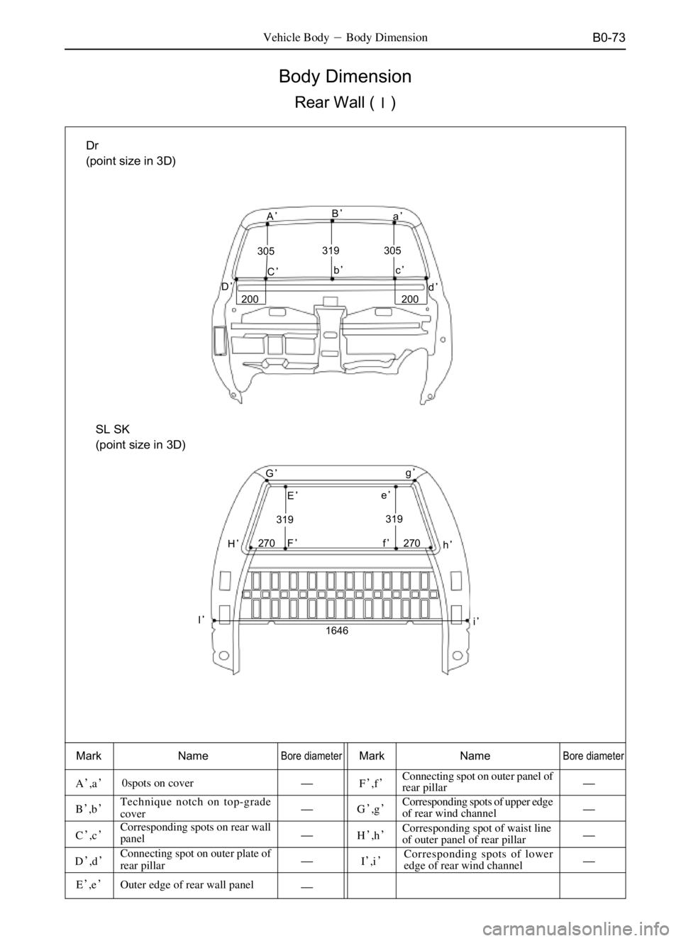
Body Dimension
Rear Wall (�)
Vehicle Body�Body Dimension
Mark NameBore diameterMark NameBore diameter
A�,a�0spots on cover====�F�,f�Connecting spot on outer panel of
rear pillar====�
B�,b�Technique notch on top-grade
cover====�G�,g�Corresponding spots of upper edge
of rear wind channel====�
C�,c�Corresponding spots on rear wall
panel====�H�,h�Corresponding spot of waist line
of outer panel of rear pillar====�
D�,d�Connecting spot on outer plate of
rear pillar====�I�,i�Corresponding spots of lower
edge of rear wind channel====�
E�,e�Outer edge of rear wall panel====� Dr
(point size in 3D)
A�
C�c� B�
a�
d� b�
D� 319
305 305
200 200
G�
319 E�
I�H�F�
i� g�
e�
f�
h�
319
270 270
1646
SL SK
(point size in 3D)
Page 457 of 484
B0-74
Body Dimension
Rear Wall (�)
Vehicle Body�Body Dimension
Mark NameBore diameterMark NameBore diameter
J�,j�Connecting part of outer panel of
rear wall with roof�O�,o�Corresponding spots of upper edge
�
K�,k�Lower edge of outer panel of rear
wall�P�,p�Vertical corresponding spot of
floor�
L�,l�Lines and angle of rear side wall
�Q�,q��
M�,m�Upper angle of rear lamp cavity
�R�,r�Outer edge of lock box at tailgate
�
N�,n�Lower angle of rear lamp cavity
�
J�
k� K� 1022j�
1270 1202
376
SY SJ
(point size in 3D)
GN O�o
m� Q�q
N�
n�
P�p
R�r M�900 L�
1042
1376 1141l�
*1: SY 1376
SJ 1385
SF
(point size in 3D)
Page 459 of 484
B0-76
Body Dimension
Side wall (�)
Vehicle Body�Body Dimension
Mark NameBore diameterMark NameBore diameter
i�,iTechnical notch on outer panel of
front pillar�n�,nTechnical notch on outer panel of
lower side beam�
j�,jTechnical notch on outer panel of
upper side beam�o�,oTechnical notch on outer panel of
lower side beam�
k�,kTechnical notch on outer panel of
upper side beam�p�,pCorresponding spot of outer panel
of middle pillar�
l�,lCorresponding spot of outer panel
of rear pillar�q�,qWiring hole of outer panel of
middle pillar�
m�,mTechnical notch on outer panel of
lower side beam�r�,rTechnical hole on outer panel of
front pillar�
i�i
650j�j
p�p
l�l
n�nq�q
m�m
o�ok�k
1108 1138
1138
=TUR
SL SK
(point size in 3D)
i�i
1108 650
1063
1160
1063
785 j�jk�k
l�l
m�m q�q
n�n r�rp�p
SY
(point size in 3D)
Page 460 of 484
B0-77
Body Dimension
Side wall(�)
Vehicle Body�Body Dimension
Mark NameBore diameterMark NameBore diameter
r�,rTechnical notch on outer panel of
front pillar�w�,w�
s�,sTechnical notch on outer panel of
upper side beam�x�,xCorresponding hole of outer panel
of middle pillar�
t�,tCorresponding spot of outer panel
of middle pillar�y�,yCorresponding spot of outer panel
of lower side beam�
u�,uCorresponding spot on outer panel
of upper side beam�z�,zTechnical hole on outer panel of
front pillar�
v�,vCorresponding spot of outer panel
of rear pillar�
SJ
(point size in 3D)
r�r
646s�su�u
t�t
v�v
w�w y�yx�x z�z
1080
11101080
965
Corresponding spot of outer panel
of lower side beam
Page:
< prev 1-8 9-16 17-24