Page 217 of 484
 Before starting the engine, tread down the br")
BR-6
Operation test of vacuum booster
Remark: check the operation of vacuum booster with the
vacuum booster tester if workable.
1.Operation inspection
(a) Before starting the engine, tread down the brake pedal
several times, and check the pedal reservation distance to
ensure there is no change occurs.
(b) Tread down the brake pedal and start the engine. If the
treaded pedals continue to move downward, which means
the operation is normal.
1. Inspection on Air-tight
(a) Start the engine for 1-2 min and then turn it off. Then
tread down the brake pedal slowly for several times, if the
pedal move downward continuously in the first, but
return gradually in the second or third time, which means
the vacuum booster has a good air-tight.
(b) Tread down the brake pedal when the engine is working,
then stop the engine, but tread the pedal down. If the
reservation distance doesnít change within the 30 seconds,
which shows the air tight of vacuum booster is good.
Air-bleeding of braking system
Remark: air-bleeding is required if any operation for braking
system is conducted or the pipe line is doubted to have air.
1. Fill the oil cup with the brake liquid
Check the liquid level of oil cup after the air in each wheel
brake pump is exhausted. If necessary, add the brake liquid.
2. Connect the vinyl resin pipe with the vent screws.
Insert the other end of pipe into the container with half brake
liquid.
Remark: the air-bleeding shall begin from the longest pipe line
when the wheel-brake cylinder is exhausting the air.
3. Air exhaust of the pipe line in braking system
(a) Tread down brake pedal slowly several times.
(b) Loosen the vent screws until the brake liquid flows out
while letting the assistant tread down the pedal. Then
screw up the vent screws.
(c) Repeat this approach until there is no air in the liquid.
4. Repeat the approach for the wheel-brake cylinder.
normal
abnormal
the third time
the second time
the first time
Braking System �Inspection and Adjustment
Page 219 of 484
BR-8Braking System�Master Cylinder
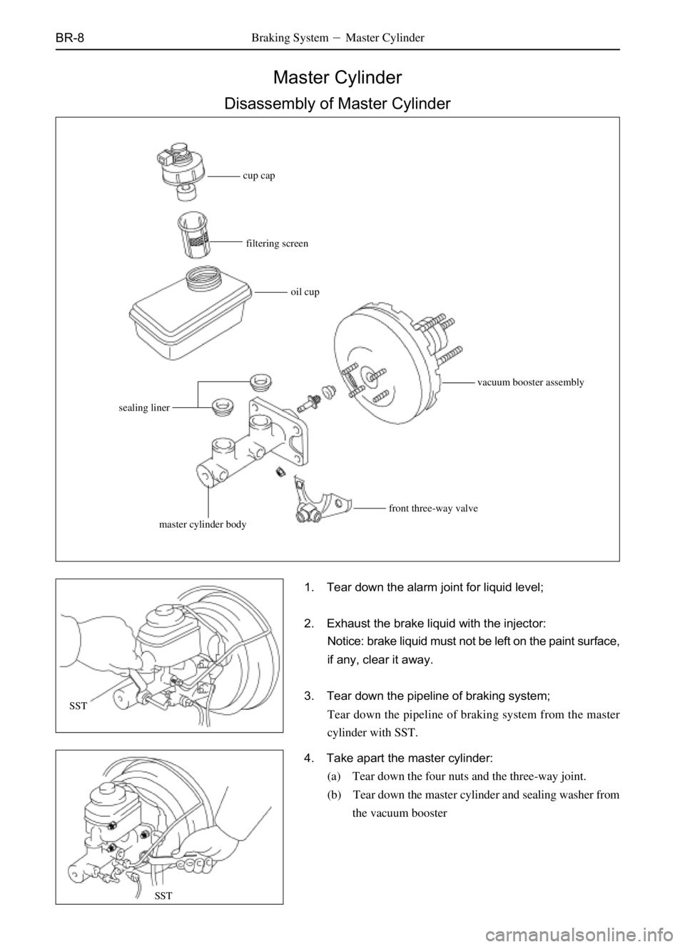
Master Cylinder
Disassembly of Master Cylinder
1. Tear down the alarm joint for liquid level;
2. Exhaust the brake liquid with the injector:
Notice: brake liquid must not be left on the paint surface,
if any, clear it away.
3. Tear down the pipeline of braking system;
Tear down the pipeline of braking system from the master
cylinder with SST.
4. Take apart the master cylinder:
(a) Tear down the four nuts and the three-way joint.
(b) Tear down the master cylinder and sealing washer from
the vacuum booster
cup cap
filtering screen
oil cup
vacuum booster assembly
sealing liner
master cylinder bodyfront three-way valve
SST
SST
Page 220 of 484
BR-9Braking System�Master Cylinder
Mount of Master Cylinder
1. Adjust the length of vacuum booster pushrod before
mounting the master cylinder;
2. Mount the master cylinder:
Mount the master and sealing washer on the vacuum booster
with four nuts.
3. Connect the two pipelines of braking system;
Mount the brake pipeline on the master cylinder with SST and
screw up the nuts.
Fastening torque�
Dr SF�(18�2)N�m
SL SK SY SJ�(19�1)N�m
4. Connect the alarm switch joint for liquid level;
5. Fill the oil cup with brake liquid and exhaust the air in
the brake pipeline;
6. Check to see whether there is brake liquid leakage;
7. Check and adjust the brake pedal.
SST
SST
Page 258 of 484

SR-2
Notice
The parts change should be conducted correctly because
any error will affect the properties of steering system, or lead
to accidental or damage when driving.
Troubleshooting
Trouble Causes Inspection items
Unsuitable tire inflation
Insufficient lubricant
Over-large inclination
Steering gear joint wear
Lower swing arm ball head wear
Steering column seize-up
Steering gear unsuitable adjustment or damage
Power steering conveyer looseness
Over-low liquid level in oil cup of steering pump
Failure in power steering mechanismInflate the tire to specified pressure
Lubricating the hanging devices
Check the Alignment of Front Wheel
Change the Steering gear joint
Change the lower swing arm ball
head;
Check the steering column
Adjust or repair the gear.
Adjust the conveyor.
Check the steering pump oil cup
Check the power steering devices
Poor returning
Unsuitable tire inflation
Insufficient lubricant
Incorrect wheel alignment
Steering column seize-up
Steering gear unsuitable adjustment or damageInflate the tire to specified pressure
Lubricating the hanging devices.
Check the Alignment of Front
Wheel
Check the steering column
Change the steering gear.
Over-large playFront wheel bearing wear
Steering drive shaft yoke wear
Lower swing arm ball head wear
Steering gear joint wear
Steering gear unsuitable adjustment or damageChange the front bearing
Change the steering drive shaft
Change the swing arm ball head
Change the steering gear joint
Change the steering joint
Abnormal noise
Steering drive lever looseness
Steering gear joint wear
Steering gear unsuitable adjustment or damage
Oil lack or poor sealing of steering machine.Tighten the steering drive lever
Change the steering gear joint
Change the steering gear
Add the oil or change the sealing
washer Steering system inspection
on vehicle.
Steering System�Notice and Troubleshooting
Difficulty in steering
Page 259 of 484

SR-3Steering System�On-vehicle Inspection
max play
On-vehicle Inspection
Steering wheel play
1.SR-18Check to see whether the steering wheel play is
correct;
Park the vehicle stably and align the tires in correct direction,
press the steering wheel with finger and swing it in left and
right direction. The play should not exceed the max play.
(Max play) �6�(Dr SF)
If the play is nor correct, adjust or repair the steering wheel as
requirement.
2. Adjust the steering wheel play:
(a) Align the wheel forward precisely;
(b) Loosen the locking nuts of steering gear;
(c) Rotate the adjusting screws of steering gear clockwise to
reduce the steering wheel play, while contrarotate the
adjusting screws to increase the steering wheel play.
Remark: screw the adjusting screws and enlarge the play a
little each time to check the adjusted play.
3. Check to see whether there is steering inconvenience
Rotate the steering wheel by half round in right and left
direction to check whether the play is correct, and whether the
wheel runs smoothly or any seize-up in its running.
4. Fix the adjusting screws and fasten the adjustable nut.
Oil level height
Check the oil level height in the steering gear housing.
Oil level height: flush with the filler opening.
If there oil is insufficient, add the gear oil and check to see
whether there is oil leakage.
Page 269 of 484

tensioning wheelpower steering oil
pump
crankshaftOn-vehicle inspection
Inspection on tension of driver conveyor
Measure the tension of driv")
SR-13Steering System�Power Steering (On-Vehicle Inspection)
tensioning wheelpower steering oil
pump
crankshaftOn-vehicle inspection
Inspection on tension of driver conveyor
Measure the tension of drive conveyor.
Drive conveyor tension: under the condition of 98 N.
New conveyor: (5-7)mm
Old conveyor:�(7-9)mm
Remark:
ìnew conveyorî means the conveyor that is used on the
machine less than five minutes;
ìold conveyorî means the conveyor that is used on machine
more than five minutes
Check for height of liquid level
1. Keep the body in horizontal status
2. Increase the liquid temperature
When the engine runs idly by 1000 r/m or less, rotate the
steering wheel several times from the locking position to the
reverse locking position to increase the liquid temperature.
3. Check to see whether there is foam or emulsification;
Remark: the foam or emulsification shows there is air in the
system or the liquid level is over-low.
4. Check the liquid level height in oil cup;
Check the liquid level height and, if needed, add the oil.
Page 270 of 484

Change of power steering liquid
1. Tear down the oil-returning hose from the oil cup to
drain the liquid into the container;
2. Run the engi")
SR-14Steering System�Power Steering (On-Vehicle Inspection)
Change of power steering liquid
1. Tear down the oil-returning hose from the oil cup to
drain the liquid into the container;
2. Run the engine in the idle status, and rotate the
steering wheel toward the max rotating angle for
several times in right or left direction while draining the
liquid, until the oil in steering liquid is drained up.
3. Turn off the engine.
4. Connect the oil-returning pipe and inject the new
power steering liquid in the liquid tank;
Hydraulic oil type: No.8 Liquid drive oil (Q/SH003.01.012-88)
5. Start the engine, and make it running in the idle status.
Rotate the steering wheel to the max rotating angle repeatedly
several times, meanwhile, supplement new power steering
liquid in the liquid tank until there is no foam or turbidities in
the liquid tank, and the oil indicating lamp reaches the marked
range when the engine is turned off.
6. Tighten the liquid tank cover
7. Exhaust the air in the power steering system;
Ai-r bleeding in power steering system
1. Check the liquid level height in the liquid tank
Check the liquid level and, if needed, supplement the liquid.
2. Start the engine in the idle status and rotate the
steering wheel repeatedly to the max rotating angle
several times.
3. Turn off the engine and connect the ethane pipe and
bleeding plug.
4. Start the engine and rotate the steering wheel
repeatedly to the max rotating angle several times.
5. Locate the steering wheel at the intermediate position.
Page 271 of 484
SR-15Steering System�Power Steering (On-Vehicle Inspection)
6. Exhaust the air in steering system:
(a) Loosen the bleeding plug;
(b) Screw up the bleeding plug when there is no air bubble
exhausted from the pipeline.
Notice: take care not let the ethane pipe slide from the
bleeding plug, because the liquid is high in temperature
and pressure.
7. Check to see whether there is air bubble or turbidities
in the oil cup, and ensure the liquid level will not
exceed the max value when the engine stops,
Measure the liquid height under the condition of engine running,
then turn off the engine and measure the liquid height again.
In case any problem is found, repeat the approaches of (5) and
(6) in Power Steering Liquid Change. If the problem still
exists, repair the power steering oil pump.
RPM RPM