Page 413 of 484
 Flush the arc lines of the front and rear ends of trim")
B0-30
Top-grade SY
SJ
SJ Top-grade SYVehicle Body�Wheel-Trims Wrapping Angle and Exterior Trim Panel
2. Mount the trim panel at front door;
(a) Flush the arc lines of the front and rear ends of trim panel
at front door in consistent with the door waist line, and the
rear end should flush with the rear end of front door, but
the front end should not interfere with the wing panel.
(b) Tap the positions of six clipes of trim panel at front door
manually to mount it on.(SJ)
Mount the five screws at upper part after aligning the
holes, and mount the five screws at lower part from the
inside, then stick the luminous strip. (top-grade SY)
Change of rear Wheel-trims
1. Tear down the rear Wheel-trims;
Tear down the three screws and take down the rear Wheel-
trims and the adhesive strip of Wheel-trims. (SY)
Take down the rear Wheel-trims after tearing down the three
screws. (SJ)
Tear down the three screws and uncover the luminous strip on
rear Wheel-trims, take down the rear Wheel-trims after tearing
down the two screws. (top-grade SY)
Change of trim panel at rear door
1. Tear down the trim panel at rear door
Take down the trim panel at rear door after tearing down one
screw and four clipes. (SJ)
Uncover the luminous strip to tear down the four screws, and
then open the rear door to tear down the four screws inside so
as to take down the trim panel at rear door. (top-grade SY)
Top-grade SY
2. Mount the trim panel at rear door
Tap the positions of four clipes of trim panel at rear door
manually to mount it on, meanwhile mount the one screw at
upper part of rear edge. (SJ)
Mount the four screws at upper part after aligning the holes,
and mount the four screws at lower part from the inside, then
stick the luminous strip. (top-grade SY)
2. Mount the front Wheel-trims
(a) Flush the front end of rear Wheel-trims with the edge line
of rear door, the rear end of the Wheel-trims with the rear
wrapping angle, the seam should be smooth with even
transmission. (top-grade SY SJ)
(b) Mount the three screws (and mount two screws at the
position where the luminous strip is stickled).
Page 414 of 484

B0-31
Top-grade SYVehicle Body�Wheel-Trims Wrapping Angle and Exterior Trim PanelChange of rear wrapping angle
1. Tear down the rear wrapping angle;
Tear down the three nuts, one screw and one self-drilling
screw, and then take down the rear wrapping angle, the rear
mudguard and the adhesive strip. (SY)
Tear down the four screws and then take down the rear small
Wheel-trims. (SJ)
Tear down one screw and three bolts to take down the rear
wrapping angle (top-grade SY)
2. Mount the rear wrapping angle
(a) Parallel the rear wrapping angle with the body waist line,
and contact the body with rear bar closely. (the adhesive
strip of wheel trims of SY model vehicle should be
pressed tightly and evenly)
(b) Mount two bolts through the body bracket, wrapping
angle and mudguard, and another bolts should be mounted
to connect the rear bar bracket and the wrapping angle.
Then mount on one screw and one self-drilling screw.
(SY)
Flush the rear small Wheel-trims and the rear Wheel-
trims, then mount on the four screws (SJ)
Mount on one screw and the other three bolts through the
body bracket, rear bar and wrapping angle. (top-grade
SY)
Notice: the parts mentioned above should be carefully
disassemble or assemble to avoid of paint face scrape
Page 436 of 484

1. Disconnect the cable of accumulator from the negative
polar;
2. Tear down the steering wheel;
3. Tear down the combined swit")
B0-53Vehicle Body�Instrument Panel
Dismantle of instrument panel
(Dr SF)
1. Disconnect the cable of accumulator from the negative
polar;
2. Tear down the steering wheel;
3. Tear down the combined switch shell cluster;
4. Tear down the bonnet lock switch;
Tear down the two screws and the sliding fastener of bonnet
lock.
5. Tear down the central bottom-wall (Dr)
Tear down the decorative cover of gearbox (SF)
6. Tear down the instrument cover (SF).
Tear down the two screws and the cover.
7. Tear down the lower instrument cover;
(a) Tear down the ignition lock;
(b) Tear down the five screws and the cover;
Tear down the four screws and the cover;
(c) Disconnect the plugging elements.
8. Tear down the air-conditioner controlling panel;
(a) Pull out the air-conditioner controlling button;
(b) Prize out the A/C switch;
(c) Prize out the air-conditioner panel as shown in the
drawing with screwdriver and take it down.
Notice: the screwdriver should be wrapped with adhesive
strap at its head before using.
(d) Disconnect the plugging elements.
9. Tear down the decorative cover of instrument (Dr)
(a) Tear down the two screws to pull out the decorative cover
of instrument;
(b) Disconnect the plugging elements.E�F
Page 438 of 484
 Tear down the three screws and the instrument panel.
(b) Disconnect the plugging elements.
SF:
(a) Tear down the fixing")
B0-55Vehicle Body�Instrument Panel
19. Tear down the instrument panel body;
(a) Tear down the three screws and the instrument panel.
(b) Disconnect the plugging elements.
SF:
(a) Tear down the fixing bolts at the ends of instrument panel
body to pull out the fixed clipes at the front end.
(b) Disconnect the plugging elements.
SL SK SJ SY
1. Disconnect the cable of accumulator from the negative
polar (-):
2. Tear down the steering wheel;
3. Tear down the combined switch shell cluster;
4. Tear down the bonnet lock switch;
Tear down the two screws and the sliding fastener of bonnet
lock.
5. Tear down the lower instrument cover;
6. Tear down the lower decorative frame of the instrument
panel;
Prize out the decorative frame of instrument with screwdriver
and take it down.
Notice: the screwdriver must be wrapped with adhesive
strap at its head before using.
7. Tear down the decorative cover of instrument;
(a) Tear down the three screws to pull out the decorative
cover of instrument.
(b) Disconnect the plugging elements.
8. Tear down the ashtray cluster;
9. Tear down the central cover;
(a) Tear down the three screws to pull out the central cover;
(b) Disconnect the plugging elements
Page 461 of 484
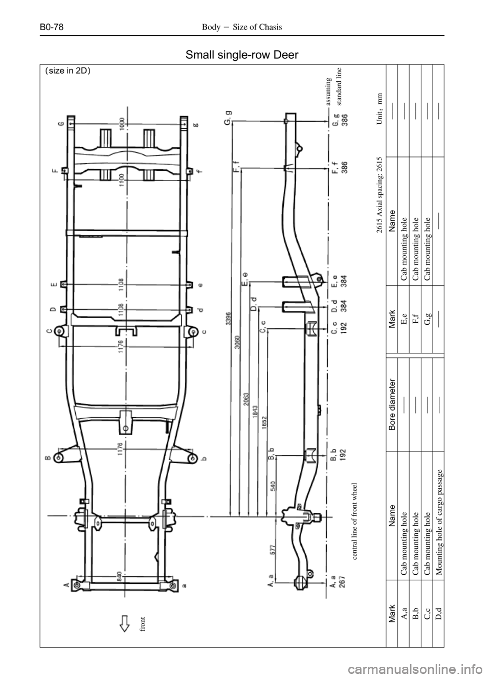
B0-78Body�Size of Chasis
Unit�mm
�size in 2D�
Small single-row Deer
Cab mounting hole
Mark
A,a
B,b
C,c
D,dName
Cab mounting hole
Cab mounting hole
Mounting hole of cargo passageBore diameter Mark
E,eName
Cab mounting hole
F,f
G,gCab mounting hole
Cab mounting hole
������
2615 Axial spacing: 2615
��
��
�� ��
��
��
��
central line of front wheelassuming
standard line front
��
Page 462 of 484
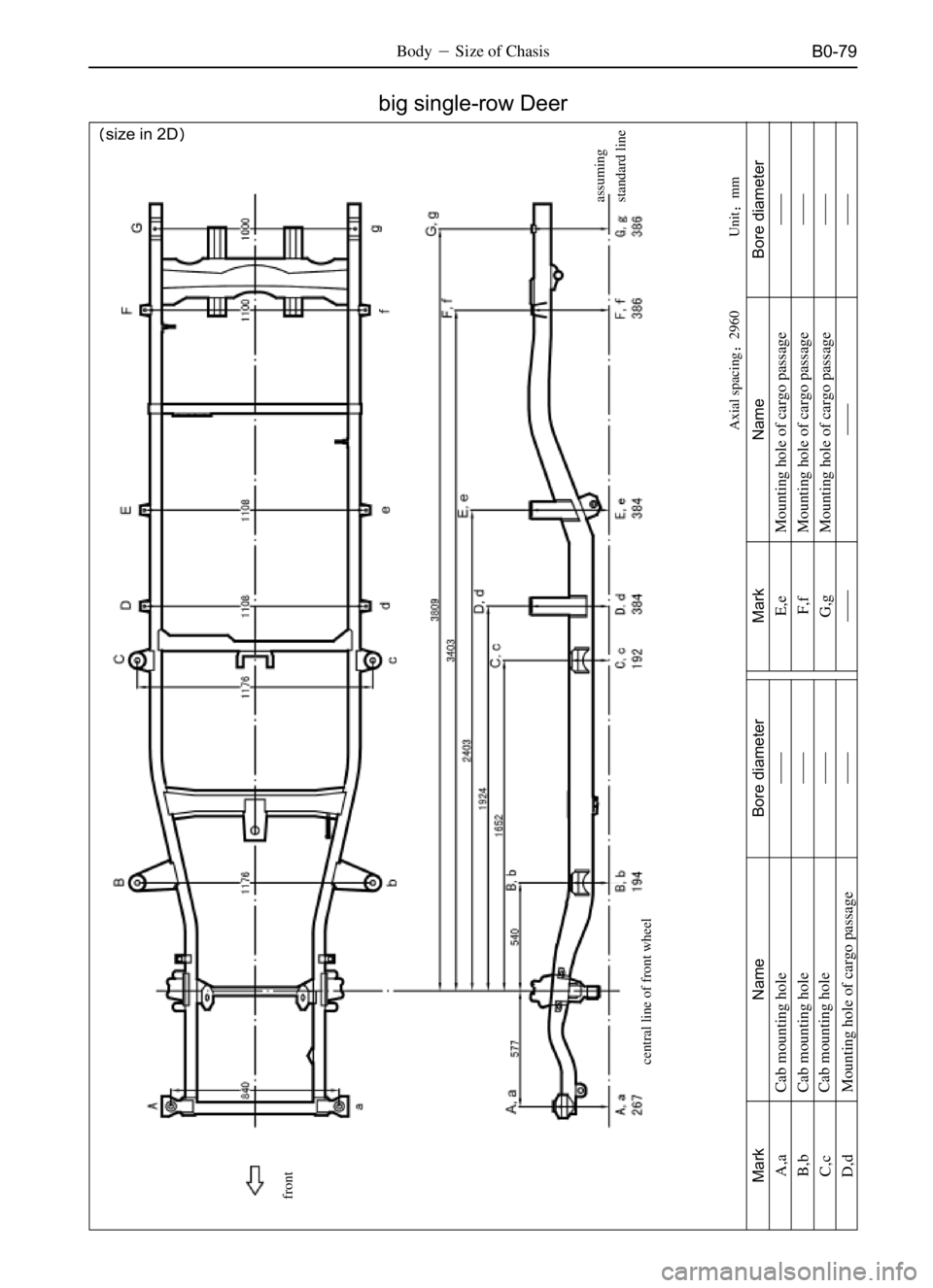
B0-79Body�Size of Chasis
Unit�mm
�size in 2D�
Mark
A,a
B,b
C,c
D,dName
Cab mounting hole
Cab mounting hole
Cab mounting hole
Mounting hole of cargo passageBore diameter
��
��
�� ��
Mark NameBore diameter
��
��
��
�� Mounting hole of cargo passage
Mounting hole of cargo passage
Mounting hole of cargo passage E,e
F,f
G,g
����
assuming
standard line front
Axial spacing�2960
big single-row Deer
central line of front wheel
Page 463 of 484
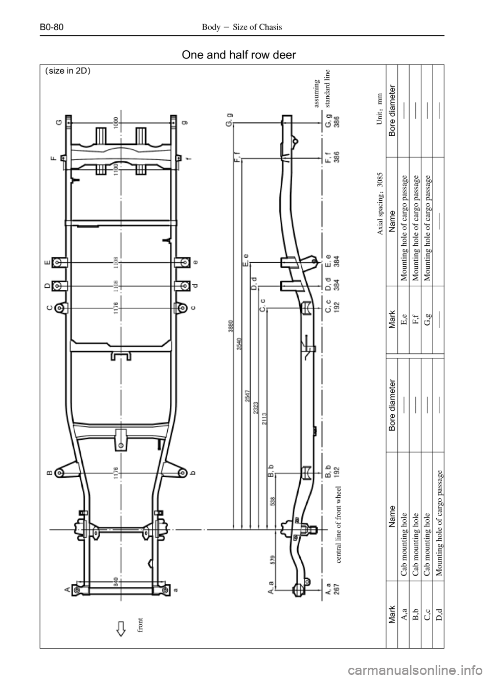
B0-80Body�Size of Chasis
Unit�mm
�size in 2D�
One and half row deer
Axial spacing�3085assuming
standard line
Mark
A,a
B,b
C,c
D,dName
Cab mounting hole
Cab mounting hole
Cab mounting hole
Mounting hole of cargo passageBore diameter
��
��
�� ��
Mark NameBore diameter
��
��
��
�� Mounting hole of cargo passage
Mounting hole of cargo passage
Mounting hole of cargo passage E,e
F,f
G,g
����
central line of front wheel front
Page 464 of 484
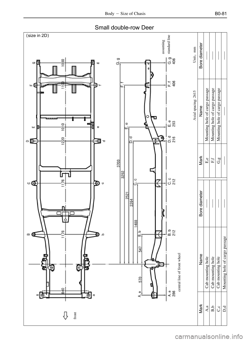
B0-81Body�Size of Chasis
Unit�mm
�size in 2D�
Small double-row Deer
Axial spacing: 2615assuming
standard line
central line of front wheel
Mark
A,a
B,b
C,c
D,dName
Cab mounting hole
Cab mounting hole
Cab mounting hole
Mounting hole of cargo passageBore diameter
��
��
�� ��
Mark NameBore diameter
��
��
��
�� Mounting hole of cargo passage
Mounting hole of cargo passage
Mounting hole of cargo passage E,e
F,f
G,g
����
front