Page 206 of 484
SA-95
Rear Differential
Element Figure
half axle gear
thrust gasket differential housing
pin
planetary
gear shaftplanetary gear
stop gaskethalf-axle gearplanetary gear
1. Tear down the speed reducer and the differential
assembly.
2. Tear down the differential from the speed reducer and
differential assembly.
Change of Differential Parts
1. Disassembly of Differential
(a) Tap out the pin with hammer and pinch.
Suspension System and Automobile Axle (Rear)�Rear differential
(b) Tear down the planetary gear shaft, the planetary gear,
planetary gear stop gasket, half-shaft gear and half axle
gear thrust gasket.
Page 207 of 484
 Put the half-axle gear thrust gasket on the half-axle gear
and then encase them in the differential housing.
(b) Encase the planetary gear stop gasket, planetary")
SA-96
2. Assembly of Differential
(a) Put the half-axle gear thrust gasket on the half-axle gear
and then encase them in the differential housing.
(b) Encase the planetary gear stop gasket, planetary gear and
encase the planetary gear shaft.
(c) Check the clearance between the half-axle gear thrust
gasket and the differential housing.
Remark: the half-axle gear and the planetary gear should run
freely without stagnant, push the planetary gear inside, then
measure the clearance between the half-axle gear thrust gasket
and the differential housing with dial indicating lamp.
Reasonable clearance range: (0.45-0.75)mm.
Remark: if the clearance value fails to fall within the above
range, change the half axle gear thrust gasket, at the same time,
ensure the left and right half axle gear thrust gasket are same
in thickness.
(d) Tap the pin in the pinhole, and rivet the end of the pinhole
so as to prevent from the pin missing.
Mount of Differential
1. Encase the differential assembly in the speed reducer
housing.
2. Mount the speed reducer and differential.
Suspension System and Automobile Axle (Rear)�Rear differential
Page 208 of 484
SA-97Suspension System and Vehicle Axle�Rear Suspension (Leaf Spring Type)
Rear suspension(leaf spring)
Leaf spring and shock absorber
N�m�specified torque
90�10
110�10
liner
rront ear pinrear ear pin liner
u-shaped bolt
spring seat
90�10
Dismantle of leaf spring and vibration
damper
1. Raise the vehicle body with a jack and support it with a
bracket;
(a) Raise the vehicle body with a jack and support it with a
bracket;
(b) Lower the axle housing until the leaf spring is loosened
to the degree there is no tension existing. Keep the leaf
spring in such status.
2. Tear down the vibration damper.
Page 209 of 484
SA-98
3. Tear down the U-shaped bolt;
(a) Tear down the mounting nuts of U-shaped bolts.
(b) Tear down the spring seat;
(c) Tear down the U-shaped bolts.
4. Tear down the leaf spring;
(a) Tear down the mounting nuts of front ear pin;
(b) Tear down the front ear pin;
(c) Disconnect the leaf spring from the bracket;
(d) Tear down the rear ear pin and the leaf, and then take
apart the leaf spring.
Change of leaf spring
1. Loosen the spring clip;
Loosen the spring clip with a chisel.
2. Tear down the central bolt;
Clamp the spring with a table vice at the position near to the
central bolt to take apart the central bolt.
3. Change the spring clip if necessary;
(a) Cut the rivet-head with a drill-head and tap the rivet out.
(b) Tap a new rivet in the hole of leaf spring and spring clip
and rivet it with pressure machine. Suspension System and Vehicle Axle�Rear Suspension (Leaf Spring Type)
Page 210 of 484
SA-99
4. Mount the central bolt of leaf spring;
(a) Align the bolt with the spring hole after clamping the
steel spring with a table vice.
(b) Mount on and tighten the spring central bolt.
Tighten torque:�(50�5)N�m
5. Bend the spring clip to a correct angle.
Bend the spring clip to the correct position with a hammer.
Mount of leaf spring
1. Mount the steel spring;
(a) Encase the front end of leaf spring into the front bracket;
(b) Mount on the bolt of front ear pin.
(c) Screw on the nut of front ear pin with fingers;
(d) Encase the rear end of leaf spring into the rear bracket and
mount on the rear ear pin.
(e) Mount on the leaf and tighten the nuts with fingers.
2. Mount the U-shaped bolt;
(a) Mount the U-shaped bolt on the axle housing.
(b) Mount the spring seat and nut under the steel spring.
(c) Tighten the mounting nut of U-shaped bolt.
Tightening moment: (110�0)N�m
Suspension System and Vehicle Axle�Rear Suspension (Leaf Spring Type)
Page 211 of 484
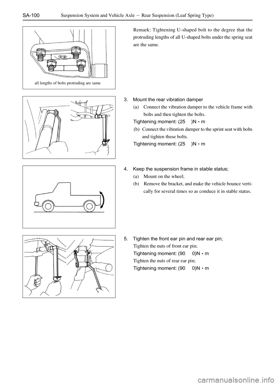
SA-100Suspension System and Vehicle Axle�Rear Suspension (Leaf Spring Type)
Remark: Tightening U-shaped bolt to the degree that the
protruding lengths of all U-shaped bolts under the spring seat
are the same.
3. Mount the rear vibration damper
(a) Connect the vibration damper to the vehicle frame with
bolts and then tighten the bolts.
Tightening moment: (25�)N�m
(b) Connect the vibration damper to the sprint seat with bolts
and tighten these bolts.
Tightening moment: (25�)N�m
4. Keep the suspension frame in stable status;
(a) Mount on the wheel;
(b) Remove the bracket, and make the vehicle bounce verti-
cally for several times so as conduce it in stable status.
5. Tighten the front ear pin and rear ear pin;
Tighten the nuts of front ear pin;
Tightening moment: (90�0)N�m
Tighten the nuts of rear ear pin;
Tightening moment: (90�0)N�m
all lengths of bolts protruding are same
Page 437 of 484
 Tear down the four screws;
Tear down the two screws;
(b) Disconnect the plugging elements;
(c) Tear down the combinatio")
B0-54Vehicle Body�Instrument Panel
10. Tear down the combination instrument;
(a) Tear down the four screws;
Tear down the two screws;
(b) Disconnect the plugging elements;
(c) Tear down the combination instrument.
11. Tear down the ashtray cluster;
12. Tear down the central cover;
(a) Tear down the decorative frame;
(b) Tear down the three screws to pull out the central cover;
(c) Disconnect the plugging elements.
13. Tear down the central panel;
(a) Prize out the central panel as shown in the drawing with
screwdriver to take it down.
Notice: the screwdriver must be wrapped with adhesive strap
at its head before using.
(b) Disconnect the plugging elements.
14. Tear down the air-conditioning controlling mechanism
assembly;
Tear down the two screws, which will let the air-conditioning
controlling mechanism in suspension.
15. Tear down the air-controlling panel;
(a) Tear down the four screws to pull out the air-condition-
ing panel;
(b) Disconnect the plugging element;
16. Tear down the CD device or the combined acoustic
device;
(a) Tear down the four screws.
(b) Disconnect the aerial cable and the plugging elements.
(c) Tear down the CD device or the combined acoustic device.
17. Tear down the glove box;
Tear down the two screws and the glove box.
SF
Seize the flanges at two ends of glove box into the sliding
channel of the glove box.
18. Tear down the central air tunnel;
Tear down the four screws and the central air tunnel.
Page 439 of 484
 Tear down the four screws;
(b) Disconnect the plugging elements.
(c) Tear down the combination instrument.
11. Tear dow")
B0-56Vehicle Body�Instrument Panel
10. Tear down the combination instrument;
(a) Tear down the four screws;
(b) Disconnect the plugging elements.
(c) Tear down the combination instrument.
11. Tear down the CD or combined acoustic device;
(a) Tear down the four screws;
(b) Disconnect the aerial cable and the plugging elements;
(c) Tear down the CD or the combined acoustic device.
12. Tear down the central air tunnel;
Tear down the four screws to take out the central air tunnel.
13. Tear down the air-conditioner controlling panel;
(a) Pull out the air-conditioner controlling button;
(b) Prize out the A/C switch;
(c) Prize out the air-conditioner controlling panel as shown
in the drawing with screwdriver and take it down.
Notice: the screwdriver should be wrapped with adhesive
strap at its head before using.
(d) Disconnect the plugging elements.
14. Tear down the air-conditioning controlling mechanism
assembly;
Tear down the two screws and let the air-conditioner control-
ling mechanism in suspension.
15. Tear down the lower covering board at right end;
Tear down the four screws and take out the lower covering
board at right end.
16. Tear down the glove box;
Tear down the two screws and the glove box
17. Tear down the instrument body;
(a) Tear down the three bolts and the instrument panel;
(b) Disconnect the plugging elements.
Mount of instrument panel
Mount the parts of instrument panel in the reverse
approach.


 Tear down the mounting nuts of U-shaped bolts.
(b) Tear down the spring seat;
(c) Tear down the U-shaped bolts.
4. Tear down the leaf spring;
(a) Tear down th")
 Align the bolt with the spring hole after clamping the
steel spring with a table vice.
(b) Mount on and tighten the spring central bolt.
Tighten tor")