Page 198 of 484
SA-87
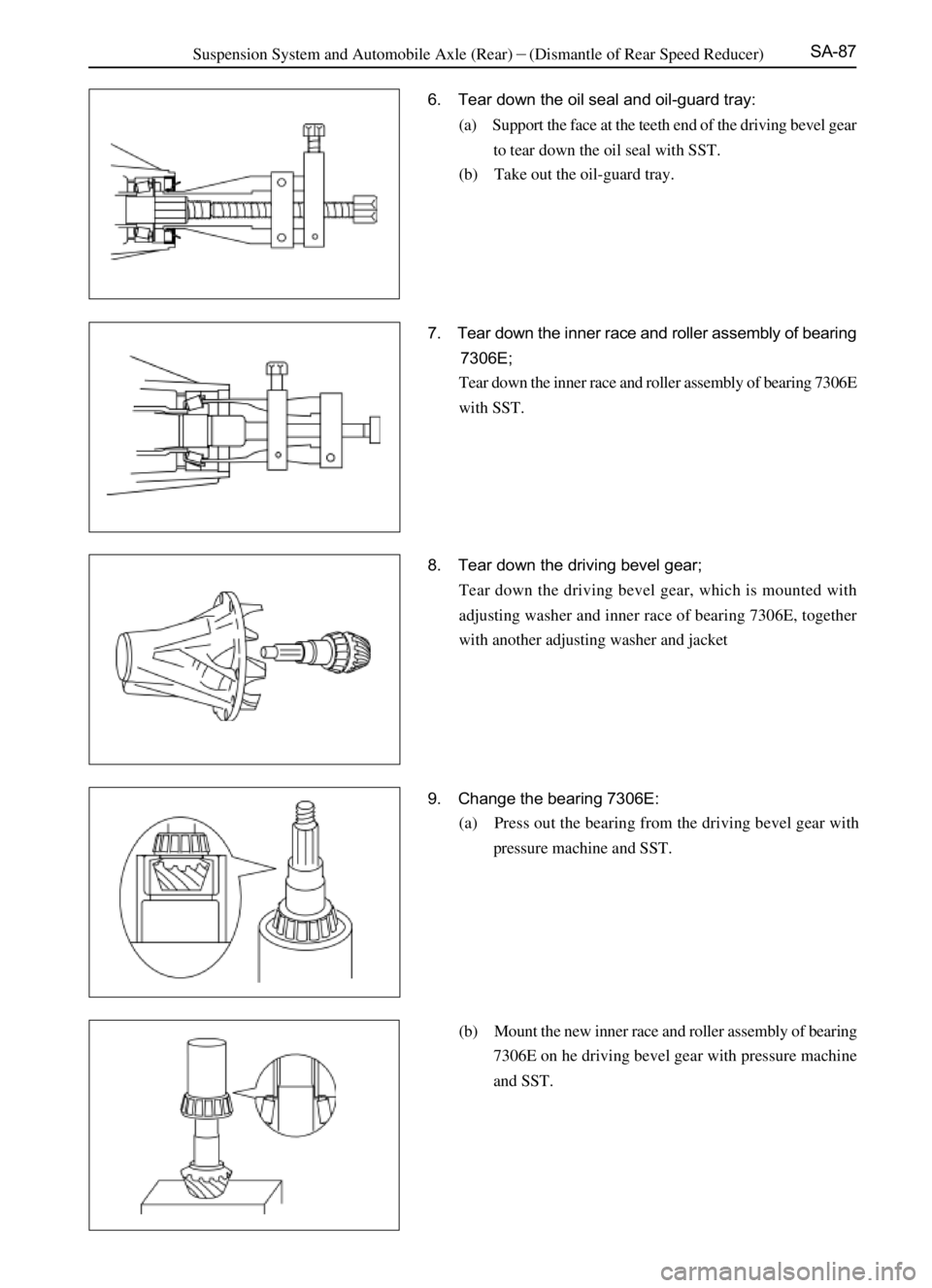
6. Tear down the oil seal and oil-guard tray:
(a) Support the face at the teeth end of the driving bevel gear
to tear down the oil seal with SST.
(b) Take out the oil-guard tray.��
7. Tear down the inner race and roller assembly of bearing
7306E;
Tear down the inner race and roller assembly of bearing 7306E
with SST.
8. Tear down the driving bevel gear;
Tear down the driving bevel gear, which is mounted with
adjusting washer and inner race of bearing 7306E, together
with another adjusting washer and jacket
9. Change the bearing 7306E:
(a) Press out the bearing from the driving bevel gear with
pressure machine and SST.
(b) Mount the new inner race and roller assembly of bearing
7306E on he driving bevel gear with pressure machine
and SST.
Suspension System and Automobile Axle (Rear)�(Dismantle of Rear Speed Reducer)
Page 199 of 484
SA-88
10. Change for the bearing 7306E and the outer race of
bearing 7607E:
(a) Tap out the bearing outer race with hammer and copper
bar.
(b) Press in the new bearing outer race with pressure ma-
chine and SST.
12. Tear down the axle driven bevel gear.
(a) Tear down the lock plate and bolts on the axle driven
bevel gear.
(b) Mark the assembly marks on the axle driven bevel gear
and the differential housing.
(c) Tap down the axle driven bevel gear with rubber hammer
and copper bar.
11. Tear down the inner race and roller assembly of bearing
200719E from differential.
Pull out the inner race and roller assembly of bearing 200719E
from the differential housing with SST. Suspension System and Automobile Axle (Rear) �(Dismantle of Rear Speed Reducer)
Page 200 of 484
 Put the inner race and roller assembly of bearing 7306E in
the speed")
SA-89
Assembly of Rear Speed Reducer
1. Mount the inner race and roller assembly of bearing
7306E, oil-guard tray and oil seal.
(a) Put the inner race and roller assembly of bearing 7306E in
the speed reducer housing, and put the oil-guard tray on it.
(b) Coat the lithium base grease on the position of speed
reducer where oil seal locates and on the lips of oil seal,
align the oil seal and press it to mount.
2. Mount the flange and dust cover assembly
Encase the flange and dust cover assembly in the speed reducer
housing, then flat it by hand.
3. Mount the driving bevel gear:
(a) Put the adjusting washer, jacket on the driving bevel gear,
which is mounted with adjusting washer and inner race
and roller assembly of bearing 7607E, then encase the
driving bevel gear in the speed reducer housing.
(b) Screw up the nuts to tighten the flange, flat washer and
the driving bevel gear with SST, and the thread locking
agent is required to be coated when screwing.
Tightening moment�(140�160)N�m
4. Measure the pre-tightening torque of the bearing:
New bearing�(1.2-1.7)N�m
The reused bearing�(0.9-1.3)N�m
Remark: if the requirement is not satisfied, change the adjust-
ing washer under jacket until the requirement is satisfied.
(a) If the measure value is smaller than the standard one,
reduce the thickness of adjusting washer;
(b) If the measure value is larger than the standard one,
increase the thickness of adjusting washer.
Suspension System and Automobile Axle (Rear) �(Dismantle of Rear Speed Reducer)
Page 201 of 484
 Mount on the lock plate and screw up the bolts to the
specified torque.
Tightening moment�(65-95)N�m
Notice: screw up the bol")
SA-90
5. Mount the axle driven bevel gear on the differential housing:
(a) Mount on the lock plate and screw up the bolts to the
specified torque.
Tightening moment�(65-95)N�m
Notice: screw up the bolts diagonally.
(b) Tighten the lock plate with hand hammer and flat head
pinch.
6. Mount the inner race and roller assembly of bearing
200719E;
Mount the bearing inner race and roller assembly in differen-
tial housing with the pressure machine and SST.
7. Mount the differential assembly;
Mount the differential in the speed reducer housing.
When mounting the differential that hasnít changed the inner
race and roller assembly of bearing 200719E, ensure the outer
race of the left and the right bearings that has disassembled
should match with their inner racers respectively.
8. Mount the adjusting ring;
Adjust the clearance between the driving bevel gear and the
axle driven bevel gear to the moderate size. And press the
bearing outer race to flatten it with adjusting ring, and then
screw up moderately.
Notice: the two adjusting rings should be adjusted
synchronically in the movement of same direction.
Suspension System and Automobile Axle (Rear) �(Dismantle of Rear Speed Reducer)
Page 202 of 484
 Align the assembly marks on differential bearing cover
and the speed reducer housing, and press down the
differential bearing by hand.
(b) Mount o")
SA-91
9. Mount on the differential bearing cover:
(a) Align the assembly marks on differential bearing cover
and the speed reducer housing, and press down the
differential bearing by hand.
(b) Mount on the double-eared stop washer and the hex nut.
10. Adjust the clearance between the driving bevel gear and
the axle driven bevel gear
(a) Screw up the hex nuts connecting the differential bearing
cover to the specified torque.
Tightening moment�(80-110)N�m
(b) Attach the measuring meter seat on the face of speed
reducer housing with the measuring head touching the
teeth face, run the axle driven bevel gear with hand to
measure the teeth engagement clearance, and then com-
pare it with the clearance value in step (d) to decide the
order of the adjusting ring tightening according to the
values.
(c) Adjust and screw up the adjusting rings with SST.
Tightening moment�(115-135)N�m
(d) Check the engagement clearance again until the clear-
ance value of the three spots evenly locates on the
circumference of axle driven bevel gear. Otherwise,
adjusting ring adjustment is suggested.
Engagement clearance�(0.13-0.25)mm
Suspension System and Automobile Axle (Rear) �(Dismantle of Rear Speed Reducer)
Page 203 of 484

SA-92
tooth top engagement
select the adjusting washers that make the main teeth apart from the axle driven bevel gear.
teeth convex =teeth concave11. Check the engagement situation of the axle driven bevel
gear and the driving bevel gear:
(a) Coat four teeth locating on different spots of axle driven
bevel gear with red powder.
(b) Rotate the axle driven bevel gear in different directions.
(c) Check the teeth engagement situation.
The teeth trace of axle driven bevel gear should satisfy
this requirement. If not, select the suitable adjusting
washer to correct according to the poor teeth engagement
situation.
Washer thickness (unit: mm) see the following table: Suspension System and Automobile Axle (Rear)�Rear Speed Reducer (Disassembly of Speed Reducer)
heel end engagement
toe end engagement
teeth root engagement select the adjusting washer that make the main teeth
contact the axle driven bevel gear more closer.
Group NO. Washer thickness Group NO. Washer thickness
1 1.60 7 1.90
2 1.65 8 1.95
3 1.70 9 2.00
4 1.75 10 2.05
5 1.80 11 2.10
6 1.85 12 2.15
Page 204 of 484
 If the engagement trace satisfies the requirement, lock
tightly the double-eared stop washer with hand hammer
and pi")
SA-93
12. Lock the double-eared stop washer to mount the stop
gasket and bolts:
(a) If the engagement trace satisfies the requirement, lock
tightly the double-eared stop washer with hand hammer
and pinch.
(b) Mount on the stop gasket, spring gasket and bolts, and
then screw up the bolts.
Tightening moment�(18-26)N�m
(c) Tap in he adjusting ring with the pinch and hammer.
13. Measure the total preload:
Preload: (1.8-2.4) N�m
If the preload is beyond the specified range, change the gas-
kets between the jacket and bearing 7607E, until they meet
the requirement.
(a) If the preload is larger than the specified value, change
the adjusting washer.
(b) If the preload is smaller than the specified value, screw up
the nuts again slowly but not exceed 160N.m.
Notice: if the screwing torque exceeds the max torque,
change the adjusting washer and repeat the preload
process. Do not screw back the main-tooth nut to reduce
the preload.
14. Check and adjust the flange bouncing
(a) Attach the dial indicating lamp seat on the speed reducer
housing with the measuring head contact the flange face,
run the flange to observe the swing out range of the dial
indicating lamp hand.
Radial full bouncing tolerance�0.10mm
Remark: the two bouncing values should be controlled within
0.10 mm, as for the parts of bounce exceeding the tolerance,
loosen the nut-driving bevel gear to assembly them in another
angle, measure the bounce value again. Observe carefully the
swing direction of the hands, which can be referred when
changing the locations of flange and the driving bevel gear. If
the requirement cannot be satisfied after several trials, change
the new flanges until the requirement is met. Suspension System and Automobile Axle (Rear)�Rear Speed Reducer (Disassembly of Speed Reducer)
30mm
15. Rivet the driving bevel gear nuts.s
Page 205 of 484
N�m
Remark: in case the sealing gask")
SA-94
Mount of Rear Speed Reducer and
Differential Assembly
1. Mount the speed reducer and differential assembly on
the rear axle housing.
Tightening moment�(18-26)N�m
Remark: in case the sealing gasket is mounted, it should be
checked to see whether it is damaged before mounting, if
damaged, change with the new sealing gasket, and the dam-
aged sealing gasket should be clear away; if no sealing gasket
is mounted, no mount is required to mount. Clean the contact
face of the mounted axle housing and coat it with silicon-
rubber plain sealing agent.
2. Connect the drive shaft and flange well and be careful to
align the assembly marks marked when disassembling.
Tightening moment�(69-79)N�m
Screw up the oil drain plug with the Tightening moment
of (140-150)N�m
Mount on the half-shaft and the brake assembly to adjust the
brake oil path so that the wheel brake pump is filled with brake
liquid.
3. Inject in the heavy-duty oil.
Oil brand: heavy-duty oil graded GL-5;
Viscosity: SAE 85W/90
Oil volume: add the oil until it overflows from the oil filler
outlets.
Screw up the oil-filling plug.
Tightening moment�(140-150)N�m
Suspension System and Automobile and Axle (Rear)�Rear speed reducer (Mount of Rear Speed Reducer and Differential Assembly)
 Tap out the bearing outer race with hammer and copper
bar.
(b) Press in the new bearing outer race with pressure ma-
chi")