2006 FORD TRANSIT relay
[x] Cancel search: relayPage 122 of 234

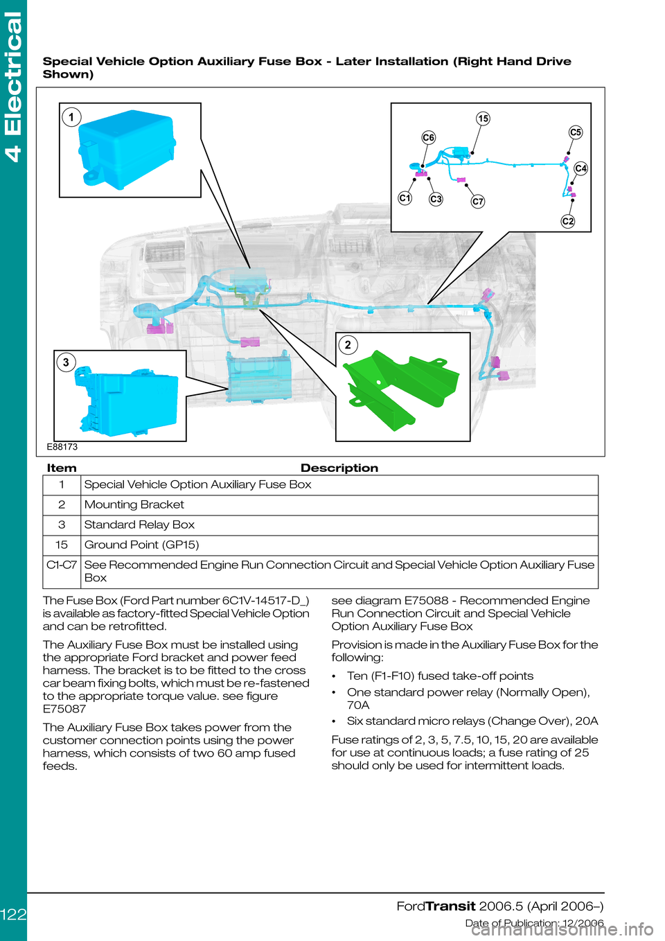
Special Vehicle Option Auxiliary Fuse Box - Later Installation (Right Hand Drive
Shown)
DescriptionItem
Special Vehicle Option Auxiliary Fuse Box1
Mounting Bracket2
Standard Relay Box3
Ground Point (GP15)15
See Recommended Engine Run Connection Circuit and Special Vehicle Option Auxiliary Fuse
Box
C1-C7
The Fuse Box (Ford Part number 6C1V-14517-D_)
is available as factory-fitted Special Vehicle Option
and can be retrofitted.
The Auxiliary Fuse Box must be installed using
the appropriate Ford bracket and power feed
harness. The bracket is to be fitted to the cross
car beam fixing bolts, which must be re-fastened
to the appropriate torque value. see figure
E75087
The Auxiliary Fuse Box takes power from the
customer connection points using the power
harness, which consists of two 60 amp fused
feeds.
see diagram E75088 - Recommended Engine
Run Connection Circuit and Special Vehicle
Option Auxiliary Fuse Box
Provision is made in the Auxiliary Fuse Box for the
following:
•Ten (F1-F10) fused take-off points
•One standard power relay (Normally Open),
70A
•Six standard micro relays (Change Over), 20A
Fuse ratings of 2, 3, 5, 7.5, 10, 15, 20 are available
for use at continuous loads; a fuse rating of 25
should only be used for intermittent loads.
FordTransit 2006.5 (April 2006–)
Date of Publication: 12/2006
4 Electrical
122E88173132
Page 123 of 234

Recommended Engine Run Connection Circuit and Special Vehicle Option Auxiliary
Fuse Box
DescriptionItem
Special Vehicle Option Auxiliary Fuse Box1
Power Mini Relay2
Micro Relay3
Central Junction Box (C4-7 = Engine Run Pin) via Jumper Harness 6C1V-14A411-F_4
Ground Point/Earth Terminal(GP15)5
Connector - Customer UseC1
Connector - to Switch Harness (6C1V-14A303)C2
Connector - To Beacon Harness (6C1V-10A993)C3
Connector - Breakout to Heating, Ventilation and Air Conditioning Harness (6C1T-18B518)C4
Connector - Breakout to Instrument Panel Harness (6C1T-14K024)C5
Connector - To Engine Run Jumper Harness (6C1V-14A411-F_)C6
Connector - To Customer Connection Points via In-line Harness (6C1V-14300-C_)C7
The configuration of the Auxiliary Fuse Box is
hard wired (as shown in Figure E75088) Auxiliary
devices should be connected via the 16-way
connector C1. Most fuse / relay configurations
are available to meet particular requirements.
A maximum of 60 A is permitted per power feed,
with maximum individual fused circuits of up to
20 A.
There are 10 possible fuse locations in the fuse
box. Please refer to the following table (Fuse
Location), which shows how the fuses are
divided between the two power feeds.
FordTransit 2006.5 (April 2006–)
Date of Publication: 12/2006
4 Electrical
123E75088
Page 125 of 234

8 Pin Connector - for Ignition, Instrument Panel Illumination and Air Conditioning
On Signals
DescriptionItem
KL15 (12V ignition feed)Pin 4
Used instead of Pin 4 on vehicles euipped with Air Conditioning)Pin 7
Instrument Panel Illumination (12V feed)Pin 6
Air Conditioning On (12V)*Pin 5
It is recommended that these signals are used
to energize relays, or any other device, as long
as the maximum current does not exceed
300mA per function, or 600mA (suitable for
powering two relays) for the ignition feed.
NOTE: *There is NO direct provision for an air
conditioning on signal. When the air-conditioning
is switched on, 12V is applied to the defrost
compressor switch and the Air conditioning low
speed blower relay (both integral to the heating
ventilation and air conditioning unit and 18B518
wiring), and the Air conditioning cycling switch
(in the engine bay as part of the 9K499 wiring
[via the 14401 and 14K024 harnesses]). Additional
load on this line is limited, so air conditioning on
is only available as a signal (300mA) for voltage
sensing or powering of a relay – powering
another device directly is Not recommended.
Where additional current is required from either
output, a standard relay should be used, please
refer to Relay Figures E75017-E75021.
The Special Vehicle Option Auxiliary Fuse Box is
recommended as the most suitable power
source for these relays. Please consult your local
National Sales Company representative for
availability.
FordTransit 2006.5 (April 2006–)
Date of Publication: 12/2006
4 Electrical
1254E84713765
Page 127 of 234

Heater Jumper for Ignition, Instrument Panel Illumination and Air Conditioning On
Signals - Later Installation
DescriptionItem
Ignition, Instrument Panel Illumination and Air Conditioning On Signals1
C4 - Connection to Heating, Ventilation and Air Conditioning Harness (18B518)2
C5 - Connection to Instrument Panel Harness (14K024)3
4.13.6 Relays and Switches
Relays
Single pole relays must be used under the
conditions:
•Single pole, 2-way (change over) is used to
switch from one circuit to another please refer
to Relay Figures E75017-E75021 for typical
relay circuit diagrams.
•Relays can be installed inside the vehicle or
inside the Special Vehicle Option Auxiliary Fuse
Box.
•The Ford standard relays have a nominal
current of 300mA (max) at 25°C. Relays with
greater loads should not be used.
•For maximum switching currents please refer
to Relay Figures E75017-E75021.
Micro Relay
FordTransit 2006.5 (April 2006–)
Date of Publication: 12/2006
4 Electrical
127E88306123 E750171425312354
Page 128 of 234

Micro Relay Parameters
20 ampsNormally open contacts
16 ampsNormally closed contacts
300 mA (max)Nominal coil current
Medium current changeover relay - Part number:6G9T-14B192-B_
Medium current normally open relay - Part number: 6G9T-14B192-A_ (pin 4 not present)
Mini relay
Mini Relay Parameters
40 ampsNormally open contacts
20 ampsNormally closed contacts
300 mA (max)Nominal coil current
Medium current changeover relay - Part number: 6G9T-14B192-D_
Medium current normally open relay - Part number: 6G9T-14B192-C_ (pin 4 not present)
Mini Power Relay
Mini Power Relay Parameters
70 ampsNormally open contacts
300 mA (MAX)Nominal coil current
High current normally open relay - Part number: 6G9T-14B192-E_
FordTransit 2006.5 (April 2006–)
Date of Publication: 12/2006
4 Electrical
128E750181234512354 E7501912351235
Page 129 of 234

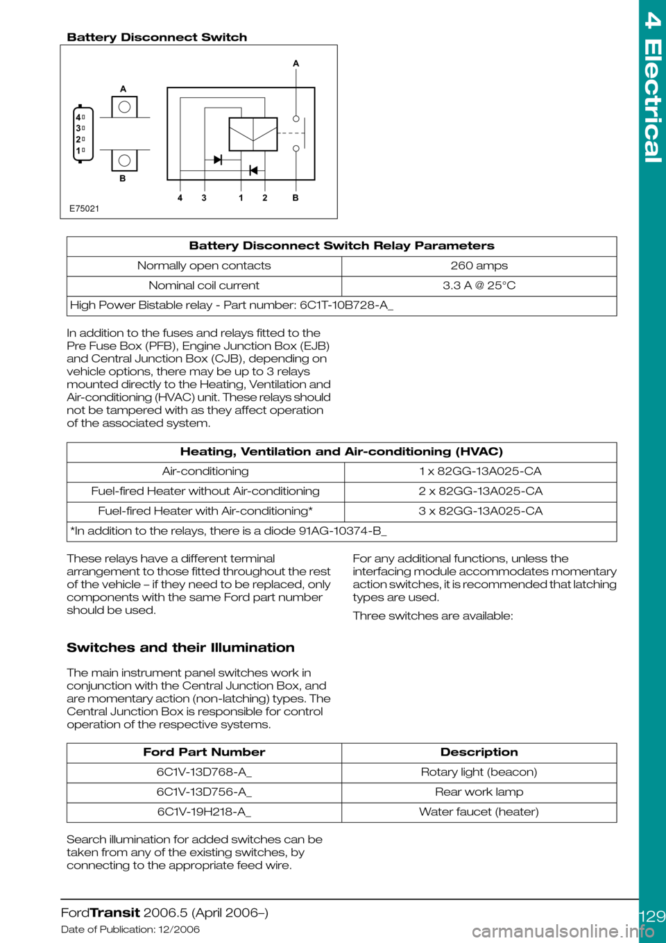
Battery Disconnect Switch
Battery Disconnect Switch Relay Parameters
260 ampsNormally open contacts
3.3 A @ 25°CNominal coil current
High Power Bistable relay - Part number: 6C1T-10B728-A_
In addition to the fuses and relays fitted to the
Pre Fuse Box (PFB), Engine Junction Box (EJB)
and Central Junction Box (CJB), depending on
vehicle options, there may be up to 3 relays
mounted directly to the Heating, Ventilation and
Air-conditioning (HVAC) unit. These relays should
not be tampered with as they affect operation
of the associated system.
Heating, Ventilation and Air-conditioning (HVAC)
1 x 82GG-13A025-CAAir-conditioning
2 x 82GG-13A025-CAFuel-fired Heater without Air-conditioning
3 x 82GG-13A025-CAFuel-fired Heater with Air-conditioning*
*In addition to the relays, there is a diode 91AG-10374-B_
These relays have a different terminal
arrangement to those fitted throughout the rest
of the vehicle – if they need to be replaced, only
components with the same Ford part number
should be used.
Switches and their Illumination
The main instrument panel switches work in
conjunction with the Central Junction Box, and
are momentary action (non-latching) types. The
Central Junction Box is responsible for control
operation of the respective systems.
For any additional functions, unless the
interfacing module accommodates momentary
action switches, it is recommended that latching
types are used.
Three switches are available:
DescriptionFord Part Number
Rotary light (beacon)6C1V-13D768-A_
Rear work lamp6C1V-13D756-A_
Water faucet (heater)6C1V-19H218-A_
Search illumination for added switches can be
taken from any of the existing switches, by
connecting to the appropriate feed wire.
FordTransit 2006.5 (April 2006–)
Date of Publication: 12/2006
4 Electrical
129E750211234AB4312BA
Page 130 of 234

4.13.7 Windscreen wipers
NOTE: Power to wiper motors is limited by the
size of the wiring and associated relays. If any
alternative wiper installation is made, it must have
a specification equivalent to Ford components.
Refer to: 5.6 Glass, Frames and Mechanisms
(page 211).
The base wiper system should not be tampered
with (controlled by Central Junction Box and
multiplex architecture).
Headlamp wash – such installations would need
to be controlled via an external timer relay. The
Special Vehicle Option Auxiliary Fuse Box should
be utilized.
Heated washer jets – aftermarket systems should
be fitted via an ignition feed, via an additional relay.
The Special Vehicle Option Auxiliary Fuse Box
should be utilized.
FordTransit 2006.5 (April 2006–)
Date of Publication: 12/2006
4 Electrical
130
Page 132 of 234

4.14.2 Engine Run Signal (D+ Alternative)
Give Away Engine-run Signal Connector (Passenger side)
WARNING: Do not cut into the
alternator wires or use the alternator
as a source to obtain a 'D+ Signal'
The Engine Run Signal will only support the basic
vehicle system.
Vehicles built from August 2006 will have a
suitable ‘give-away’ connector (6.3mm flat blade
receptacle) in the main vehicle harness. This is
located on the passenger side and can be
accessed by dropping the glove box.
Most early-build vehicles do not have this
connector. In such instances, for engine run (C4-7
on the central Junction Box), there is a dedicated
terminal (pin 16) on the passenger-door loom /
main loom in-line connector available to energize
a relay (maximum one (1) relay). A T-piece
harness (6C1V-14A411-F*) is available from your
Local Ford Dealer to fit between the door / main
loom in-line connector. If the vehicle does not
have this fitted as a factory-fitted option
(campers, for example, do have this pre-fitted),
one way to install this is:
•Remove the passenger side mirror on the
using a long-reach M8 socket (note: right hand
drive vehicles use shear bolts that will need to
be replaced)
•Pull out the flexible grommet between the
body and the door, including the connector
shroud behind it.
•The connector between the main vehicle
harness (14401) and the door jumper harness
(14A631) Can now be pulled through and
disconnected
•The T-piece jumper harness can be inserted
between the two connectors and pushed
back into the body.
•Drop the glove box fully by depressing the side
detents – the single lead with connector
(6.3mm male terminal) can be pulled through
a square hole in the body-side inner panel,
behind the flexible grommet
•Re-fitment of the flexible grommet and door
mirror is the reverse of the above process,
noting that new shear bolts will be necessary
for right hand drive vehicle, part number
W712939-S422.
This engine run signal is ground switching (max.
current sink 200mA), for example it provides no
positive output and is only active under the
following conditions:
•Ignition on
•Engine running at normal idle
•Alternator giving output
•System voltage about 9 volts
FordTransit 2006.5 (April 2006–)
Date of Publication: 12/2006
4 Electrical
132E84715