2006 FORD TRANSIT fuel
[x] Cancel search: fuelPage 88 of 234

3.8 Fuel System
WARNINGS:
Do not cut into the original fuel
supply lines
Make sure that the modified vehicle
complies with all relevant legal
requirements.
For auxiliary applications requiring a fuel supply,
it is advisable to use the auxiliary fuel supply port
as shown in the figure below.
•The auxiliary fuel supply port is mounted on
the top of the fuel sender unit located on the
top of the fuel tank, for applications such as
an auxiliary heater or fuel fired hand wash
facility.
•Ensure that a suitable fuel shut-off is fitted in
any unique system.
•Refit the Ford hose assembly from the fuel
pump to the fuel line.
•The tube and/or line must be routed
independently and secured to the body
structure or to suitable brackets.
CAUTION: Make sure that sufficient
clearance is maintained for all
driving conditions to all hot and
moving components.
NOTE: Do not fasten anything to existing
electrical components or wires
FordTransit 2006.5 (April 2006–)
Date of Publication: 12/2006
3 Powertrain
88
Page 89 of 234

Auxiliary Fuel Supply Port
DescriptionItem
Ford Motor Company Part1
Cut off top of Port on tank cap2
Insert tube into port and fix connector to tank cap3
Drive Direction4
FordTransit 2006.5 (April 2006–)
Date of Publication: 12/2006
3 Powertrain
894231E78195
Page 91 of 234

CAN-Bus System (Architecture)
Antilock Brake SystemKCentral Junction Box (Passenger Junction
Box)
A
Powertrain Control ModuleLVoice Recognition Module/Wireless
connection (blue tooth)
B
Steering Angle SensorMAudio Control Unit (Radio/CD)C*
Yaw Rate SensorNNavigation (Radio/CD)D*
Diagnostic ConnectorPRemote Keyless EntryE
Park Aid ModeQPassive Anti-Theft SystemF
Restraints Control ModuleRRain SensorG
Hybrid Electronic ClusterSBattery Backed Sounder (BBS)H
Interior Motion Sensing (IMS)J
* Either Audio Control Unit or Navigation
4.1.2 Central Junction Box (CJB)
WARNING: Unapproved and/or
incorrect connection to any of the
mating wiring can cause either the
associated systems to shut down
(overload protection), or permanent
damage to the Central Junction Box
itself.
Basic vehicle functions (for example: headlights,
front wipers) are available on all Central Junction
Boxes (CJBs). Increased vehicle features are
available on the mid- and high-level CJBs, as per
the following list:
Incremental FunctionalityCentral Junction Box (CJB)
6C1T-14A073-A_ (low)
(in addition to low level CJB)6C1T-14A073-B_ (mid)
Reverse CyclingRemote Keyless Entry
Slam LockingVIN Identification
Front Fog LightsPerimeter Alarm
Theatre Dimming (Interior Lights)Central and double Locking
Heated WindscreenZonal unlocking
Heated MirrorsAuto Locking on drive away
Rear WipersAuto Relocking on time out
Heated Rear Window(s)Crash Activated unlocking
Mis-locking feedback (audible
and visual)
(in addition to mid-level CJB)6C1T-14A073-C_ (high)
Ambient air temperature meas-
urement
Battery Backed Sounder (BBS)
Rain SensorInterior Motion Sensor (IMS)
Daytime Running LightsZonal opposite door relocking
AutolampsConfigurable unlocking
Fuel Pump Control (petrol only)CAT 1 Alarm (BBS, IMS & Rear
Glass Breakage)
Cruise control
FordTransit 2006.5 (April 2006–)
Date of Publication: 12/2006
4 Electrical
91
Page 106 of 234

4.5 Climate Control System
WARNING: Do not use propylene
glycol based coolant
•Never secure hoses or tubes to the
transmission fill or dip stick or to any fuel
system or brake component
•Do not route heater or refrigerant lines near or
directly over any exhaust system component,
including the exhaust manifolds.
•Avoid routing of hoses in the wheelhouse or
stone kick-up arch. However, if routing is
required in these areas, shield against stone
pecking as appropriate.
•Do not route hoses near sharp edges. Utilize
guards to protect against cutting or chafing.
FordTransit 2006.5 (April 2006–)
Date of Publication: 12/2006
4 Electrical
106
Page 129 of 234
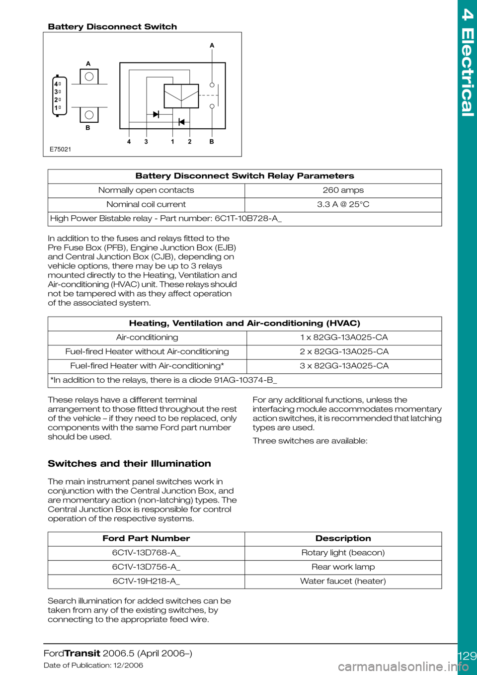
Battery Disconnect Switch
Battery Disconnect Switch Relay Parameters
260 ampsNormally open contacts
3.3 A @ 25°CNominal coil current
High Power Bistable relay - Part number: 6C1T-10B728-A_
In addition to the fuses and relays fitted to the
Pre Fuse Box (PFB), Engine Junction Box (EJB)
and Central Junction Box (CJB), depending on
vehicle options, there may be up to 3 relays
mounted directly to the Heating, Ventilation and
Air-conditioning (HVAC) unit. These relays should
not be tampered with as they affect operation
of the associated system.
Heating, Ventilation and Air-conditioning (HVAC)
1 x 82GG-13A025-CAAir-conditioning
2 x 82GG-13A025-CAFuel-fired Heater without Air-conditioning
3 x 82GG-13A025-CAFuel-fired Heater with Air-conditioning*
*In addition to the relays, there is a diode 91AG-10374-B_
These relays have a different terminal
arrangement to those fitted throughout the rest
of the vehicle – if they need to be replaced, only
components with the same Ford part number
should be used.
Switches and their Illumination
The main instrument panel switches work in
conjunction with the Central Junction Box, and
are momentary action (non-latching) types. The
Central Junction Box is responsible for control
operation of the respective systems.
For any additional functions, unless the
interfacing module accommodates momentary
action switches, it is recommended that latching
types are used.
Three switches are available:
DescriptionFord Part Number
Rotary light (beacon)6C1V-13D768-A_
Rear work lamp6C1V-13D756-A_
Water faucet (heater)6C1V-19H218-A_
Search illumination for added switches can be
taken from any of the existing switches, by
connecting to the appropriate feed wire.
FordTransit 2006.5 (April 2006–)
Date of Publication: 12/2006
4 Electrical
129E750211234AB4312BA
Page 154 of 234
harness that provides roof-mounted rear turn
indicators, powered via relays. This should be
used in conjunction with SVO fusebox.
3.Chassis cab LED rear lamp cluster
replacement recommendations, especially
turn indicator relay implications – see lighting
load table. Generally the use of LED equivalent
lighting systems reduces the electrical load on
the vehicle; however, special care needs to
be taken with respect to any change to or
addition of turn indicator lights. Depending on
the current requirements of the LED(s)
compared to the bulb it is replacing, a ballast
resistor may be required, if not already
integrated into the LED lamp assembly.
Without this, bulb outage detection for turn
indicators will be affected, which is a legal
requirement.
Additional turn indicators must be powered
through relays (max 300mA), driven by existing
turn lights. The maximum load that the Central
Junction Box can drive is 3 x 21W per side (front,
rear and CAT 6 turn indicators); but even if the
vehicle is not fitted with the CAT 6 lights, the feeds
for these should not be used as the Central
Junction Box would need reconfiguring, which
could have safety as well as functional
implications.
4.Special Vehicle Option beacon switch: wiring
locations, circuit diagrams and max amperage
– see Special Vehicle Option fuse box
schematic (max current is 15A); there is
provision for the Special Vehicle Option beacon
switch in an empty switch location on the
instrument panel.
5.Rear loom connector detail location and supply
details for retro-fit loom extension for
example:- when extending a medium wheel
base, long wheel base or extended frame
overhang, what connectors do they use to
make a plug and play loom extension? – for
chassis cab vehicles, there is an Special
Vehicle Option extension loom for rear lamps
(part number 6C1V-14408-A*). There is not, at
present, a similar loom for Van, Bus and
Kombi's, although the appropriate mating
connector is now tooled, so this would be
possible.
Miscellaneous Systems
Handbrake on - Cluster Warning Light -
Unless the vehicle is specified with options that
drive the handbrake warning light (for example
ESP, Australia market), the components making
up this system are not fitted. We do not
recommend installation of this feature as an
aftermarket addition. There are several reasons
for this:
1.Not all circuits carry the requisite wire as a give
away:
•The wires might be part of the main vehicle
harness (14401) even if not used – for example
camper vehicles are normally ordered with
power mirrors, and the wires will be present
as a give-away.
•The seat pedestal harness (14K076), however,
is vehicle specific – if the handbrake is not part
of the specification, it will not be present or
give-away. This harness would need to be
changed to the compatible part that also
includes the handbrake warning light circuit.
2.The handbrake switch (part number
2F2T-15852-A*) together with its short jumper
harness (6C1T-15K857-A*) would need to be
obtained and fitted.
3.The handbrake warning light is in all clusters,
but unless the vehicle config. parameter
“parking brake switch” is set, the Central
Junction Box will not read this input, and hence
NO CAN message sent to the cluster.
Reconfiguration can only be done at a Ford
Dealer.
NOTE: If a vehicle already has a handbrake
warning light in the cluster, or one is installed as
per the Ford design, it is not possible to utilize the
wire from the handbrake switch as part of an
interlock circuit (this is a pull up resistor input that
provides a wetting current of 20mA – anything in
excess of this, for example through additional
circuitry, will almost certainly damage the Central
Junction Box). If there is no handbrake switch
installed, it would be possible to add one and
utilize this as part of a separate circuit, up to a
maximum current of 500mA through the switch.
Reverse Sensors (Rear Park Aid
Module)- The factory-fit option is a CAN-based
system, but for Van, Bus, and Kombi vehicles
only. Stand-alone systems can be installed (for
example for chassis cab conversions), but would
need to utilize the PTA line of the radio if muting
is required.
Fuel Fired Heater (FFH)- Add FFH: wiring is
only present (give-away) in certain harnesses.
There was an aftermarket kit available for this
system on current Transit, which could probably
be “updated” to suit V347/8.
Fuel Fired Heater (FFH) - Programmable
FFH: this utilizes a timer/control module mounted
to the Instrument Panel, which necessitates
having the correct Instrument Panel harness
fitted. Retrofit of this would be a difficult.
For both systems, the appropriate 6C1T-14K132
harness would be required (suffix -A* for
Programmable FFH, and suffix –B* for Add FFH).
Central Locking
Locking is controlled by the Central Junction Box
module. There is current sensing on certain
locking circuit pins as part of the security system
– if these are tampered with, locking cannot be
guaranteed.
FordTransit 2006.5 (April 2006–)
Date of Publication: 12/2006
4 Electrical
154
Page 162 of 234
How to change the 3 pre-set default
RPM values in the 3 speed mode
1.Enter ‘learn mode’ (see directions above)
2.Arm the RPM speed controller (turn the key
switch to ‘on’)
3.Press & release the brake pedal once
4.Press & release the RPM button that requires
re-programming
5.Use the accelerator pedal to rev the engine to
the new desired RPM speed & hold at this
speed (only speeds between 1200 to 3000
rpm can be selected in 3 speed mode)
6.Press & release the same RPM button to reset
the stored RPM speed to the current engines
RPM
7.Release the accelerator pedal
8.Repeat steps 4) to 7) for the remaining RPM
buttons
The 3 RPM speeds should now be
re-programmed to the new RPM speeds. The
new settings can be saved & learn mode exited
(see below)
NOTE: If the engine RPM responds to the initial
RPM button press, then the vehicle has not
entered ‘learn mode’ correctly & you will have to
restart the procedure. If the engine stalls out at
the brake or accelerator pedal inputs then the
vehicle was not in, or has dropped out of ‘learn
mode’ & you will have to restart the procedure.
How to save new settings & exit
from ‘Learn mode’
1.From within the ‘learn mode’ & with the RPM
Speed Control switch box ‘armed’, press the
clutch pedal repeatedly until the engine stalls.
2.Restart the engine & test the new settings,
repeat above procedures if necessary
NOTE: The engine stalling indicates that the
settings should have been saved & the vehicle
has exited from ‘learn mode’. Learn mode
however is very specific that the exact steps are
taken in the correct order & within certain time
limits otherwise the learn procedure fails & it may
take several attempts to get this order & timing
correct & a successful modification from the
default settings.
Some Reasons why RPM speed
Control operation may stop or fail
The RPM Speed control software monitors
vehicle information during operation in RPM
speed control mode & will drop out of RPM speed
control and / or stall the engine should any
adverse signals be detected. For example:
•If the engine temperature becomes too hot
then RPM speed control will stop in order to
protect the engine.
•If the engine oil light illuminates then RPM
speed control will stop in order to protect the
engine
•If the low fuel level light illuminates then RPM
speed control will stop so that the vehicle can
be driven to a refueling point.
•If the vehicle speed exceeds approx 2.5 mph
wile in 3 speed or variable speed modes, then
RPM speed control may stop. RPM speed
control should normally be operated with the
hand brake on, but some uses may require a
low level of vehicle ‘creep’ during RPM speed
control operation. Note that there is no sensing
of the park brake on this version of RPM speed
controller to facilitate this type of operation.
•The software monitors for ‘stuck on’ buttons
on the control switch box, this may result in
RPM speed control being halted. A button that
is held down for too long may be registered
by the software as a ‘stuck’ button.
•The software monitors the foot pedals, if
depressed these may stall the engine if in 3
speed mode or variable speed mode (does
not apply to idle up speed)
•If the control switch box circuitry significantly
exceeds 2110 ohms or there is a short circuit
then RPM speed control will not be possible.
•If a PTO conversion has been attempted on a
vehicle with a non ABS braking system then
RPM speed control will fail due to vehicle
speed being registered via a transmission
speed sensor and / or the need to press the
clutch in order to put the vehicle in gear while
in RPM speed control mode.
4.14.10 Adding Connectors,
Terminals and Wiring
Additional Rear Speakers
NOTE: The connectors on the Instrument Panel
harness (14K024) and the main harness (14401)
are reversed between Left Hand Drive (LHD) and
Right Hand Drive (RHD) vehicles, hence different
sets of terminals/wires are required to cover all
the markets.
FordTransit 2006.5 (April 2006–)
Date of Publication: 12/2006
4 Electrical
162
Page 175 of 234

5.1 Body
5.1.1 Body Structures - General
Information
When carrying out vehicle
conversions/modifications the following points
should be considered:
•Make sure that the vehicle structural integrity
is maintained
•Do not drill into closed frame body members.
•Make sure that the design for the body
alterations or additional structure disperse the
load evenly.
CAUTION: Uneven load distribution
could result in unacceptable
handling and braking
characteristics.
•Re-paint metal edges after cutting or drilling.
All metal edges must comply with exterior and
interior protection legislation.
•All fixings through the floor, sides or roof must
be sealed.
Refer to: 5.10 Corrosion Prevention (page 221).
WARNING: Before drilling the floor,
check the no drill zones.
See figure E74574 - Floor (No Drill Zones) under
the Floor Fuel Tank.
•Make sure that fixings in the 'B'-pillar area do
not encroach on the seat belts or seat belt
reels.
For unique floor fixings, see (Frame Drilling and
Tube Reinforcing).
Refer to: 5.11 Frame and Body Mounting (page
222).
For Load Compartment Tie Downs(Load Lashing
Points).
Refer to: 5.2 (page 200).
FordTransit 2006.5 (April 2006–)
Date of Publication: 12/2006
5 Body and Paint
175