2006 FORD SUPER DUTY height
[x] Cancel search: heightPage 42 of 312
Vertical and horizontal aim adjustment (sealed beam headlamps)
The headlamps on your vehicle are intended to be aimed using
mechanical aimers. If mechanical aimers are used and the cross-car sight
line is in any way blocked, set the legs of the universal adaptor all to the
same setting, such that the cross-car sight line is no longer blocked, per
the instructions for the brand of mechanical aimer used. You can also
aim the headlamps visually using the procedure below.
To adjust the headlamps:
1. Park your vehicle on a level
surface about 25 feet (7.6 meters)
away from a vertical plain surface
(3). Check your headlamp alignment
at night or in a dark area so that
you can see the headlamp beam
pattern.
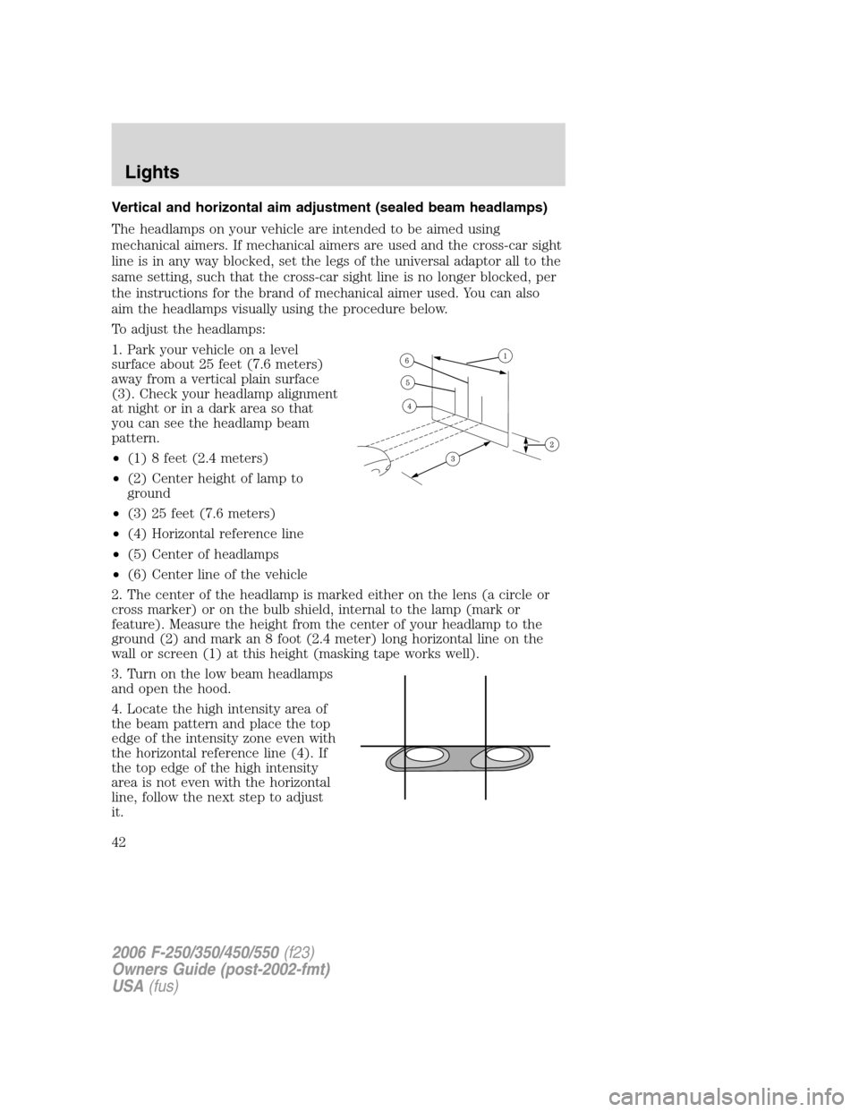
•(1) 8 feet (2.4 meters)
•(2) Center height of lamp to
ground
•(3) 25 feet (7.6 meters)
•(4) Horizontal reference line
•(5) Center of headlamps
•(6) Center line of the vehicle
2. The center of the headlamp is marked either on the lens (a circle or
cross marker) or on the bulb shield, internal to the lamp (mark or
feature). Measure the height from the center of your headlamp to the
ground (2) and mark an 8 foot (2.4 meter) long horizontal line on the
wall or screen (1) at this height (masking tape works well).
3. Turn on the low beam headlamps
and open the hood.
4. Locate the high intensity area of
the beam pattern and place the top
edge of the intensity zone even with
the horizontal reference line (4). If
the top edge of the high intensity
area is not even with the horizontal
line, follow the next step to adjust
it.
2006 F-250/350/450/550(f23)
Owners Guide (post-2002-fmt)
USA(fus)
Lights
42
Page 43 of 312
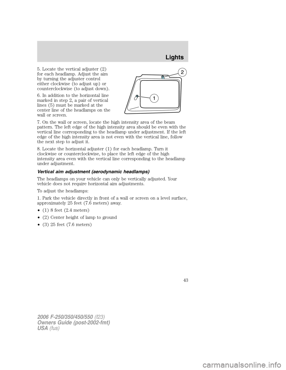
5. Locate the vertical adjuster (2)
for each headlamp. Adjust the aim
by turning the adjuster control
either clockwise (to adjust up) or
counterclockwise (to adjust down).
6. In addition to the horizontal line
marked in step 2, a pair of vertical
lines (5) must be marked at the
center line of the headlamps on the
wall or screen.
7. On the wall or screen, locate the high intensity area of the beam
pattern. The left edge of the high intensity area should be even with the
vertical line corresponding to the headlamp under adjustment. If the left
edge of the high intensity area is not even with the vertical line, follow
the next step to adjust it.
8. Locate the horizontal adjuster (1) for each headlamp. Turn it
clockwise or counterclockwise, to place the left edge of the high
intensity area even with the vertical line corresponding to the headlamp
under adjustment.
Vertical aim adjustment (aerodynamic headlamps)
The headlamps on your vehicle can only be vertically adjusted. Your
vehicle does not require horizontal aim adjustments.
To adjust the headlamps:
1. Park the vehicle directly in front of a wall or screen on a level surface,
approximately 25 feet (7.6 meters) away.
•(1) 8 feet (2.4 meters)
•(2) Center height of lamp to ground
•(3) 25 feet (7.6 meters)
2006 F-250/350/450/550(f23)
Owners Guide (post-2002-fmt)
USA(fus)
Lights
43
Page 44 of 312
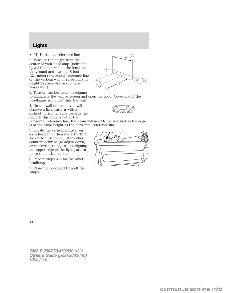
•(4) Horizontal reference line
2. Measure the height from the
center of your headlamp (indicated
by a 3.0 mm circle on the lens) to
the ground and mark an 8 foot
(2.4 meter) horizontal reference line
on the vertical wall or screen at this
height (a piece of masking tape
works well).
3. Turn on the low beam headlamps
to illuminate the wall or screen and open the hood. Cover one of the
headlamps so no light hits the wall.
4. On the wall or screen you will
observe a light pattern with a
distinct horizontal edge towards the
right. If this edge is not at the
horizontal reference line, the beam will need to be adjusted so the edge
is at the same height as the horizontal reference line.
5. Locate the vertical adjuster on
each headlamp, then use a E5 Torx
socket to turn the adjuster either
counterclockwise (to adjust down)
or clockwise (to adjust up) aligning
the upper edge of the light pattern
up to the horizontal line.
6. Repeat Steps 3–5 for the other
headlamp.
7. Close the hood and turn off the
lamps.
2006 F-250/350/450/550(f23)
Owners Guide (post-2002-fmt)
USA(fus)
Lights
44
Page 100 of 312
BELT AND RETRACTOR ASSEMBLY MUST BE REPLACED if
the seat belt assembly “automatic locking retractor” feature or
any other seat belt function is not operating properly when checked
according to the procedures in theWorkshop Manual. Failure to
replace the belt and retractor assembly could increase the risk of
injury in collisions.
Energy Management Feature
•This vehicle has a seat belt system with an energy management
feature at the front outboard seating positions to help further reduce
the risk of injury in the event of a head-on collision.
•The front outboard seat belt systems have a retractor assembly that is
designed to pay out webbing in a controlled manner. This feature is
designed to help reduce the belt force acting on the occupant’s chest.
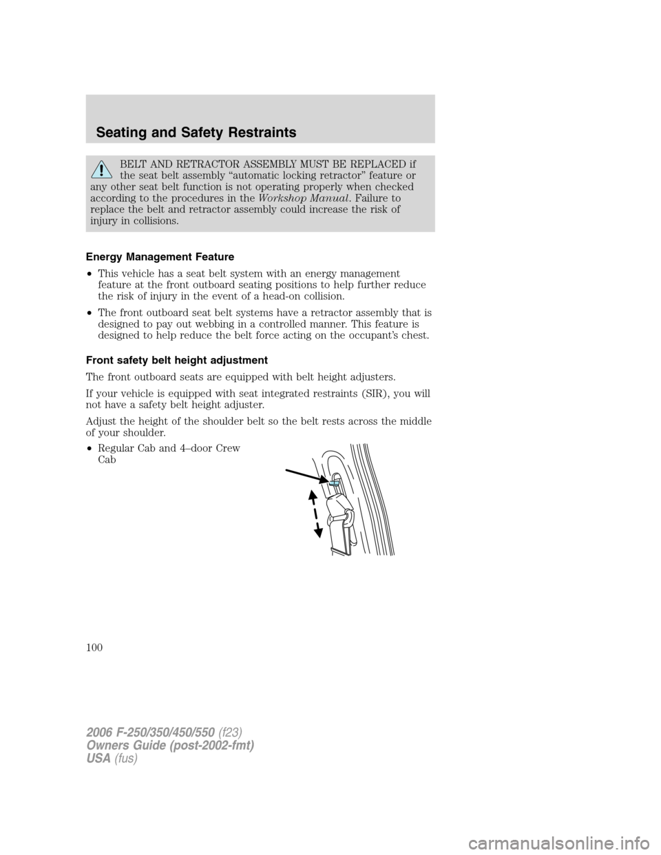
Front safety belt height adjustment
The front outboard seats are equipped with belt height adjusters.
If your vehicle is equipped with seat integrated restraints (SIR), you will
not have a safety belt height adjuster.
Adjust the height of the shoulder belt so the belt rests across the middle
of your shoulder.
•Regular Cab and 4–door Crew
Cab
2006 F-250/350/450/550(f23)
Owners Guide (post-2002-fmt)
USA(fus)
Seating and Safety Restraints
100
Page 101 of 312
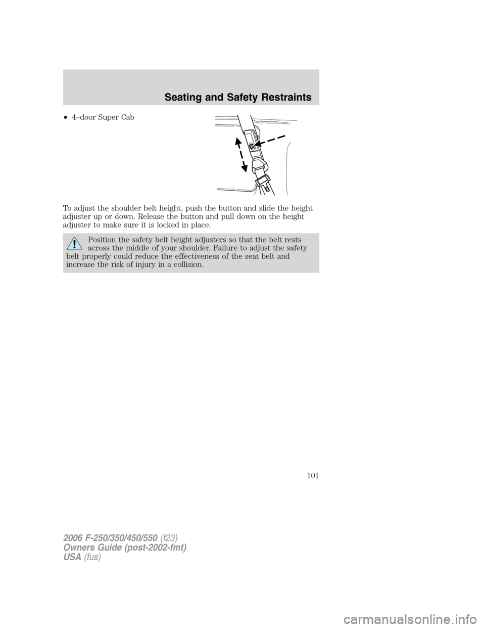
•4–door Super Cab
To adjust the shoulder belt height, push the button and slide the height
adjuster up or down. Release the button and pull down on the height
adjuster to make sure it is locked in place.
Position the safety belt height adjusters so that the belt rests
across the middle of your shoulder. Failure to adjust the safety
belt properly could reduce the effectiveness of the seat belt and
increase the risk of injury in a collision.
2006 F-250/350/450/550(f23)
Owners Guide (post-2002-fmt)
USA(fus)
Seating and Safety Restraints
101
Page 107 of 312
Do not use extensions to change the fit of the shoulder belt
across the torso.
Safety belt maintenance
Inspect the safety belt systems periodically to make sure they work
properly and are not damaged. Inspect the safety belts to make sure
there are no nicks, tears or cuts. Replace if necessary. All safety belt
assemblies, including retractors, buckles, front seat belt buckle
assemblies, buckle support assemblies (slide bar-if equipped), shoulder
belt height adjusters (if equipped), shoulder belt guide on seatback (if
equipped), child safety seat LATCH and tether anchors, and attaching
hardware, should be inspected after a collision. Ford Motor Company
recommends that all safety belt assemblies in use in vehicles involved in
a collision be replaced. However, if the collision was minor and your
authorized dealer finds that the belts do not show damage and continue
to operate properly, they do not need to be replaced. Safety belt
assemblies not in use during a collision should also be inspected and
replaced if either damage or improper operation is noted.
Failure to inspect and if necessary replace the safety belt
assembly under the above conditions could result in severe
personal injuries in the event of a collision.
For proper care of soiled safety belts, refer toInteriorin theCleaning
chapter.
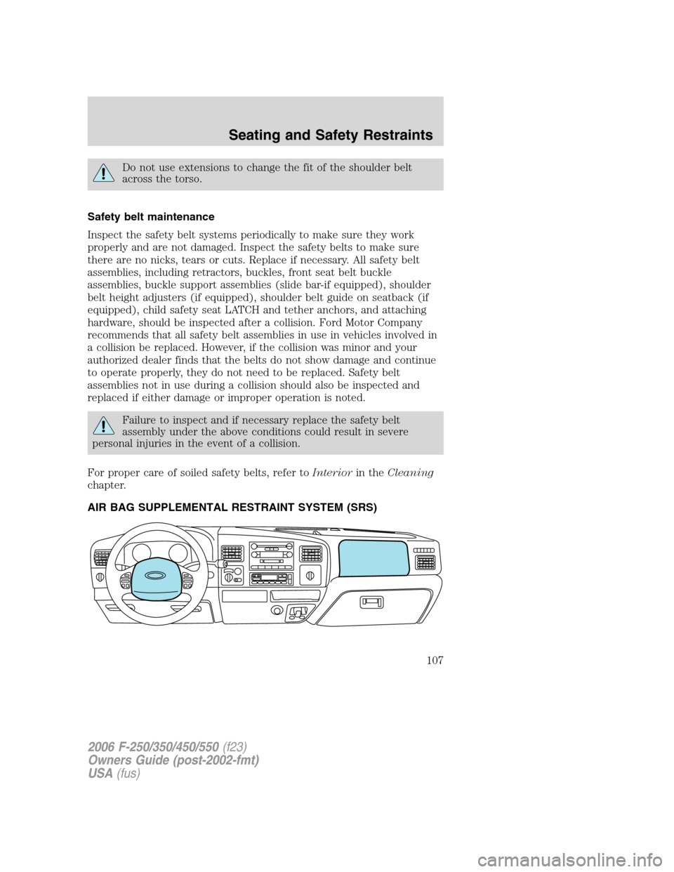
AIR BAG SUPPLEMENTAL RESTRAINT SYSTEM (SRS)
2006 F-250/350/450/550(f23)
Owners Guide (post-2002-fmt)
USA(fus)
Seating and Safety Restraints
107
Page 137 of 312
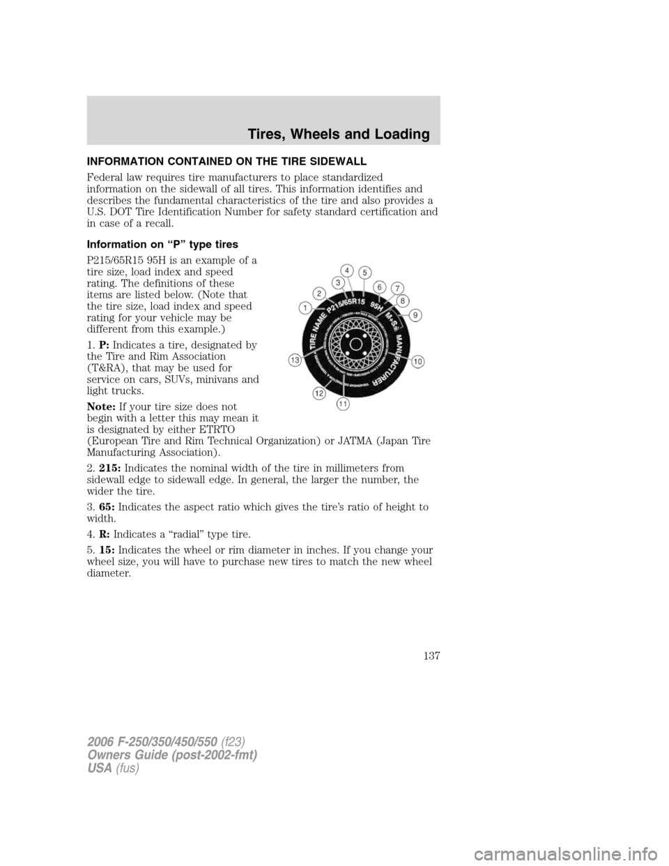
INFORMATION CONTAINED ON THE TIRE SIDEWALL
Federal law requires tire manufacturers to place standardized
information on the sidewall of all tires. This information identifies and
describes the fundamental characteristics of the tire and also provides a
U.S. DOT Tire Identification Number for safety standard certification and
in case of a recall.
Information on “P” type tires
P215/65R15 95H is an example of a
tire size, load index and speed
rating. The definitions of these
items are listed below. (Note that
the tire size, load index and speed
rating for your vehicle may be
different from this example.)
1.P:Indicates a tire, designated by
the Tire and Rim Association
(T&RA), that may be used for
service on cars, SUVs, minivans and
light trucks.
Note:If your tire size does not
begin with a letter this may mean it
is designated by either ETRTO
(European Tire and Rim Technical Organization) or JATMA (Japan Tire
Manufacturing Association).
2.215:Indicates the nominal width of the tire in millimeters from
sidewall edge to sidewall edge. In general, the larger the number, the
wider the tire.
3.65:Indicates the aspect ratio which gives the tire’s ratio of height to
width.
4.R:Indicates a “radial” type tire.
5.15:Indicates the wheel or rim diameter in inches. If you change your
wheel size, you will have to purchase new tires to match the new wheel
diameter.
2006 F-250/350/450/550(f23)
Owners Guide (post-2002-fmt)
USA(fus)
Tires, Wheels and Loading
137
Page 141 of 312
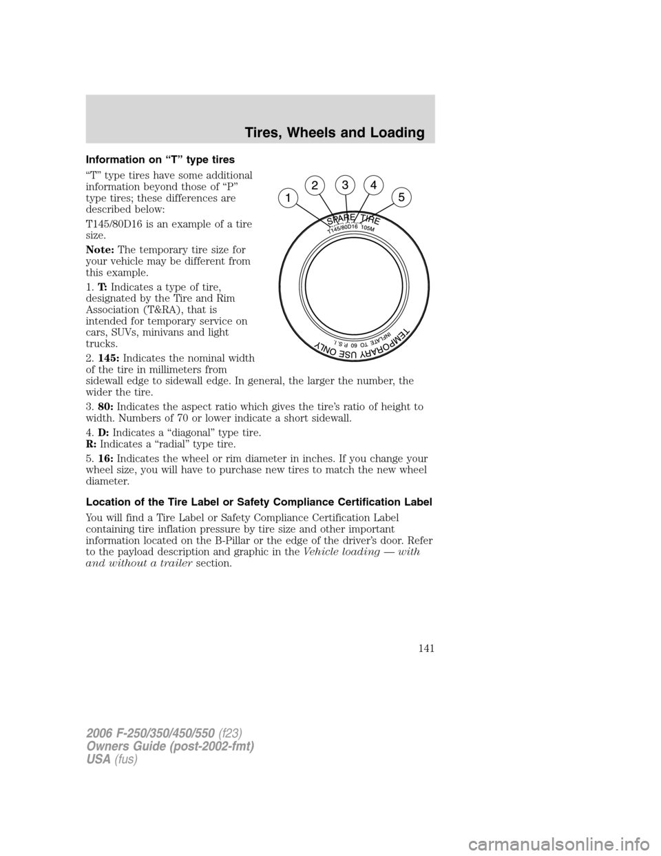
Information on “T” type tires
“T” type tires have some additional
information beyond those of “P”
type tires; these differences are
described below:
T145/80D16 is an example of a tire
size.
Note:The temporary tire size for
your vehicle may be different from
this example.
1.T:Indicates a type of tire,
designated by the Tire and Rim
Association (T&RA), that is
intended for temporary service on
cars, SUVs, minivans and light
trucks.
2.145:Indicates the nominal width
of the tire in millimeters from
sidewall edge to sidewall edge. In general, the larger the number, the
wider the tire.
3.80:Indicates the aspect ratio which gives the tire’s ratio of height to
width. Numbers of 70 or lower indicate a short sidewall.
4.D:Indicates a “diagonal” type tire.
R:Indicates a “radial” type tire.
5.16:Indicates the wheel or rim diameter in inches. If you change your
wheel size, you will have to purchase new tires to match the new wheel
diameter.
Location of the Tire Label or Safety Compliance Certification Label
You will find a Tire Label or Safety Compliance Certification Label
containing tire inflation pressure by tire size and other important
information located on the B-Pillar or the edge of the driver’s door. Refer
to the payload description and graphic in theVehicle loading — with
and without a trailersection.
2006 F-250/350/450/550(f23)
Owners Guide (post-2002-fmt)
USA(fus)
Tires, Wheels and Loading
141