Page 3 of 312
Cleaning 241
Maintenance and Specifications 249
Engine compartment 251
Engine oil 254
Battery 258
Engine Coolant 260
Fuel information 266
Air filter(s) 284
Part numbers 286
Refill capacities 287
Lubricant specifications 290
Accessories 304
Index 307
All rights reserved. Reproduction by any means, electronic or mechanical
including photocopying, recording or by any information storage and retrieval
system or translation in whole or part is not permitted without written
authorization from Ford Motor Company. Ford may change the contents without
notice and without incurring obligation.
Copyright © 2005 Ford Motor Company
Table of Contents
3
2006 F-250/350/450/550(f23)
Owners Guide (post-2002-fmt)
USA(fus)
Page 11 of 312
Vehicle Symbol Glossary
Power Windows
Front/Rear
Power Window Lockout
Child Safety Door
Lock/UnlockInterior Luggage
Compartment Release
Symbol
Panic AlarmEngine Oil
Engine CoolantEngine Coolant
Temperature
Do Not Open When HotBattery
Avoid Smoking, Flames,
or SparksBattery Acid
Explosive GasFan Warning
Power Steering FluidMaintain Correct Fluid
LevelMAX
MIN
Emission SystemEngine Air Filter
Passenger Compartment
Air FilterJack
Check fuel capLow tire pressure
warning
2006 F-250/350/450/550(f23)
Owners Guide (post-2002-fmt)
USA(fus)
Introduction
11
Page 14 of 312
after releasing the parking brake indicates low brake fluid level and the
brake system should be inspected immediately by your servicing
authorized dealer.
Driving a vehicle with the brake system warning light on is
dangerous. A significant decrease in braking performance may
occur. It will take you longer to stop the vehicle. Have the vehicle
checked by your authorized dealer immediately.
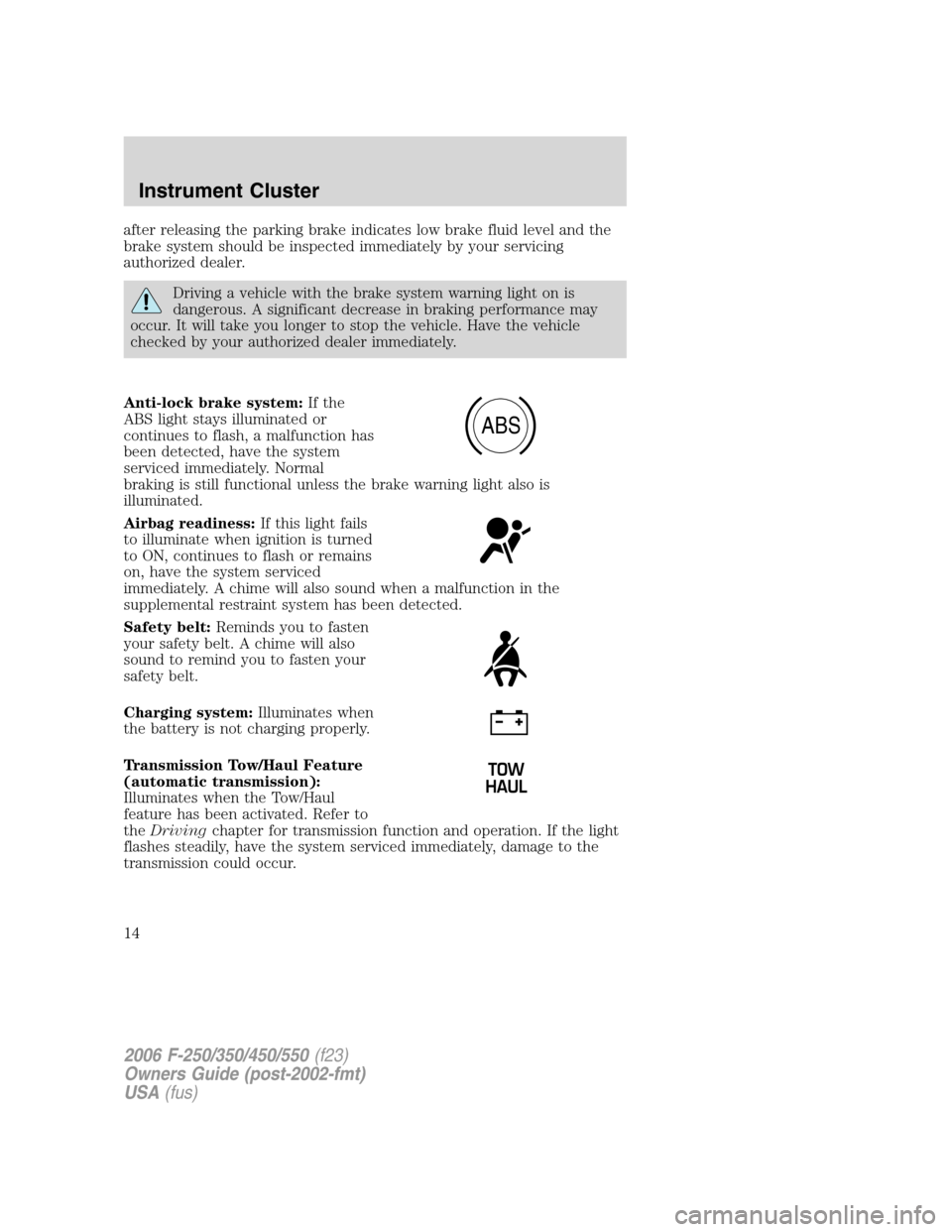
Anti-lock brake system:If the
ABS light stays illuminated or
continues to flash, a malfunction has
been detected, have the system
serviced immediately. Normal
braking is still functional unless the brake warning light also is
illuminated.
Airbag readiness:If this light fails
to illuminate when ignition is turned
to ON, continues to flash or remains
on, have the system serviced
immediately. A chime will also sound when a malfunction in the
supplemental restraint system has been detected.
Safety belt:Reminds you to fasten
your safety belt. A chime will also
sound to remind you to fasten your
safety belt.
Charging system:Illuminates when
the battery is not charging properly.
Transmission Tow/Haul Feature
(automatic transmission):
Illuminates when the Tow/Haul
feature has been activated. Refer to
theDrivingchapter for transmission function and operation. If the light
flashes steadily, have the system serviced immediately, damage to the
transmission could occur.
ABS
2006 F-250/350/450/550(f23)
Owners Guide (post-2002-fmt)
USA(fus)
Instrument Cluster
14
Page 19 of 312
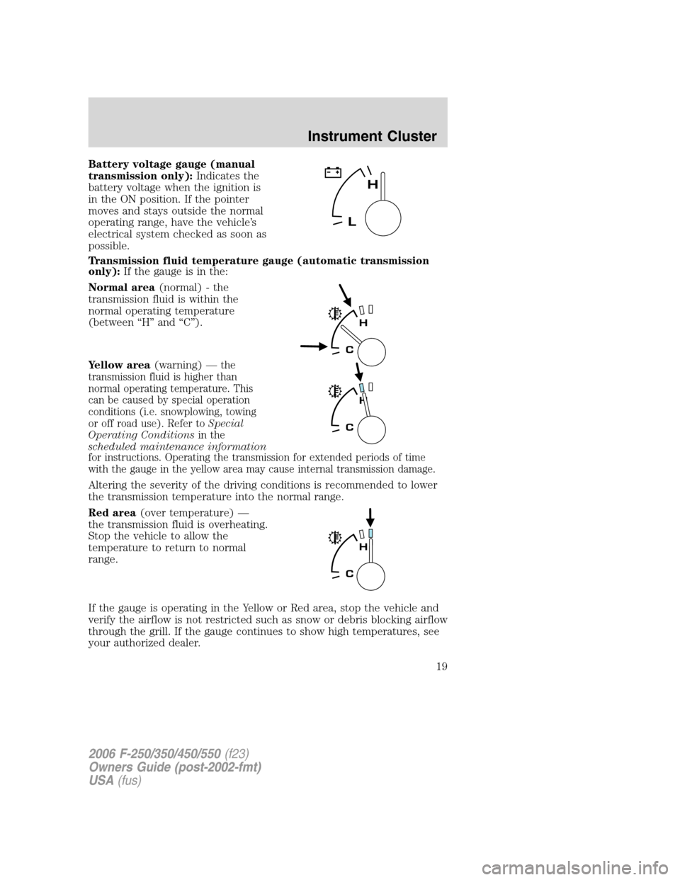
Battery voltage gauge (manual
transmission only):Indicates the
battery voltage when the ignition is
in the ON position. If the pointer
moves and stays outside the normal
operating range, have the vehicle’s
electrical system checked as soon as
possible.
Transmission fluid temperature gauge (automatic transmission
only):If the gauge is in the:
Normal area(normal) - the
transmission fluid is within the
normal operating temperature
(between “H” and “C”).
Yellow area(warning) —
the
transmission fluid is higher than
normal operating temperature. This
can be caused by special operation
conditions (i.e. snowplowing, towing
or off road use). Refer toSpecial
Operating Conditionsin the
scheduled maintenance information
for instructions. Operating the transmission for extended periods of time
with the gauge in the yellow area may cause internal transmission damage.
Altering the severity of the driving conditions is recommended to lower
the transmission temperature into the normal range.
Red area(over temperature) —
the transmission fluid is overheating.
Stop the vehicle to allow the
temperature to return to normal
range.
If the gauge is operating in the Yellow or Red area, stop the vehicle and
verify the airflow is not restricted such as snow or debris blocking airflow
through the grill. If the gauge continues to show high temperatures, see
your authorized dealer.
2006 F-250/350/450/550(f23)
Owners Guide (post-2002-fmt)
USA(fus)
Instrument Cluster
19
Page 56 of 312
AUXILIARY POWER POINT (12VDC)
Power outlets are designed for accessory plugs only. Do not insert
any other object in the power outlet for this will damage the
outlet and blow the fuse. Do not hang any type of accessory or
accessory bracket from the plug. Improper use of the power
outlet can cause damage not covered by your warranty.
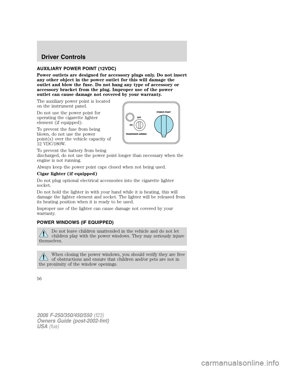
The auxiliary power point is located
on the instrument panel.
Do not use the power point for
operating the cigarette lighter
element (if equipped).
To prevent the fuse from being
blown, do not use the power
point(s) over the vehicle capacity of
12 VDC/180W.
To prevent the battery from being
discharged, do not use the power point longer than necessary when the
engine is not running.
Always keep the power point caps closed when not being used.
Cigar lighter (if equipped)
Do not plug optional electrical accessories into the cigarette lighter
socket.
Do not hold the lighter in with your hand while it is heating, this will
damage the lighter element and socket. The lighter will be released from
its heating position when it is ready to be used.
Improper use of the lighter can cause damage not covered by your
warranty.
POWER WINDOWS (IF EQUIPPED)
Do not leave children unattended in the vehicle and do not let
children play with the power windows. They may seriously injure
themselves.
When closing the power windows, you should verify they are free
of obstructions and ensure that children and/or pets are not in
the proximity of the window openings.
2006 F-250/350/450/550(f23)
Owners Guide (post-2002-fmt)
USA(fus)
Driver Controls
56
Page 64 of 312
UPFITTER CONTROLS (IF EQUIPPED)
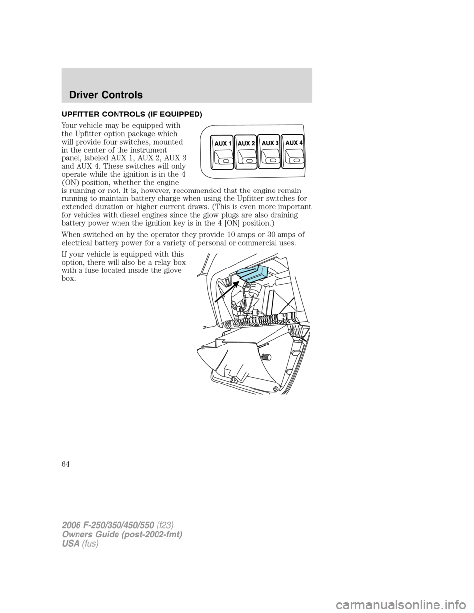
Your vehicle may be equipped with
the Upfitter option package which
will provide four switches, mounted
in the center of the instrument
panel, labeled AUX 1, AUX 2, AUX 3
and AUX 4. These switches will only
operate while the ignition is in the 4
(ON) position, whether the engine
is running or not. It is, however, recommended that the engine remain
running to maintain battery charge when using the Upfitter switches for
extended duration or higher current draws. (This is even more important
for vehicles with diesel engines since the glow plugs are also draining
battery power when the ignition key is in the 4 [ON] position.)
When switched on by the operator they provide 10 amps or 30 amps of
electrical battery power for a variety of personal or commercial uses.
If your vehicle is equipped with this
option, there will also be a relay box
with a fuse located inside the glove
box.
2006 F-250/350/450/550(f23)
Owners Guide (post-2002-fmt)
USA(fus)
Driver Controls
64
Page 72 of 312
![FORD SUPER DUTY 2006 1.G Owners Manual 7. Press the RESET control to start
the compass calibration function.
8. Slowly drive the vehicle in a
circle (less than 3 mph [5 km/h])
until the CIRCLE SLOWLY TO
CALIBRATE display changes to CALIBRA FORD SUPER DUTY 2006 1.G Owners Manual 7. Press the RESET control to start
the compass calibration function.
8. Slowly drive the vehicle in a
circle (less than 3 mph [5 km/h])
until the CIRCLE SLOWLY TO
CALIBRATE display changes to CALIBRA](/manual-img/11/5267/w960_5267-71.png)
7. Press the RESET control to start
the compass calibration function.
8. Slowly drive the vehicle in a
circle (less than 3 mph [5 km/h])
until the CIRCLE SLOWLY TO
CALIBRATE display changes to CALIBRATION COMPLETED. It will take
up to five circles to complete calibration.
9. The compass is now calibrated.
Distance to empty (DTE)
Selecting this function from the
INFO menu estimates approximately
how far you can drive with the fuel
remaining in your tank under
normal driving conditions.
Remember to turn the ignition OFF
when refueling to allow this feature to correctly detect the added fuel.
The DTE function will display LOW FUEL LEVEL and sound a tone for
one second when you have approximately 50 miles (80 km) to empty. If
you RESET this warning message, this display and tone will return
within 10 minutes.
DTE is calculated using a running average fuel economy, which is based
on your recent driving history of 500 miles (800 km). This value is not
the same as the average fuel economy display. The running average fuel
economy is reinitialized to a factory default value if the battery is
disconnected.
Average fuel economy (AFE)
Select this function from the INFO
menu to display your average fuel
economy in miles/gallon or liters/
100 km.
If you calculate your average fuel
economy by dividing miles traveled
since last fill-up by gallons of fuel used (multiply liters used by 100, then
divide by kilometers traveled), your figure may be different than
displayed for the following reasons:
•Your vehicle was not perfectly level during fill-up
2006 F-250/350/450/550(f23)
Owners Guide (post-2002-fmt)
USA(fus)
Driver Controls
72
Page 83 of 312
•the ignition is turned to the 4 (ON) position,
•unlocking the vehicle using the keyless entry keypad,
•or using the UNLOCK
control on your remote entry transmitter (if
equipped).
This feature is initially deactivated, but may be activated by taking your
vehicle to an authorized dealer.
Sounding a panic alarm
Press
to activate the alarm. Press again or turn the ignition to 4
(ON) to deactivate.
Note:The panic alarm will only operate when the ignition is in the 2
(LOCK) or 3 (OFF) position.
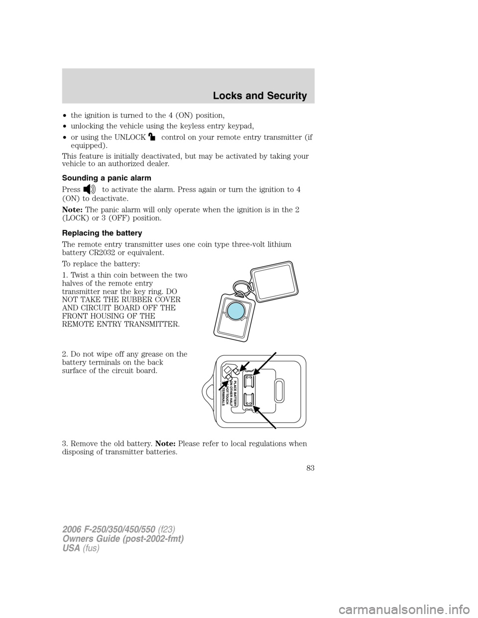
Replacing the battery
The remote entry transmitter uses one coin type three-volt lithium
battery CR2032 or equivalent.
To replace the battery:
1. Twist a thin coin between the two
halves of the remote entry
transmitter near the key ring. DO
NOT TAKE THE RUBBER COVER
AND CIRCUIT BOARD OFF THE
FRONT HOUSING OF THE
REMOTE ENTRY TRANSMITTER.
2. Do not wipe off any grease on the
battery terminals on the back
surface of the circuit board.
3. Remove the old battery.Note:Please refer to local regulations when
disposing of transmitter batteries.
2006 F-250/350/450/550(f23)
Owners Guide (post-2002-fmt)
USA(fus)
Locks and Security
83