2006 FORD SUPER DUTY ignition
[x] Cancel search: ignitionPage 156 of 312
Towing trailers beyond the maximum tongue weight exceeds the
limit of the towing system and could result in vehicle structural
damage, loss of vehicle control and personal injury.
Load equalizing hitch
When hooking up a trailer using a load equalizing hitch, always use the
following procedure:
1. Park the unloaded vehicle on a level surface. With the ignition on and
all doors closed, allow the vehicle to stand for several minutes so that it
can level.
2. Measure the height of a reference point on the front and rear bumpers
at the center of the vehicle.
3. Attach the trailer to the vehicle and adjust the hitch equalizers so that
the front bumper height is within
1�2” (13 mm) of the reference point.
After proper adjustment, the rear bumper should be no higher than in
Step 2.
Note:Adjusting an equalizing hitch so the rear bumper of the vehicle is
higher than it was unloaded will defeat the function of the load
equalizing hitch and may cause unpredictable handling.
Safety chains
Always connect the trailer’s safety chains to the frame or hook retainers
of the vehicle hitch. To connect the trailer’s safety chains, cross the
chains under the trailer tongue and allow slack for turning corners.
If you use a rental trailer, follow the instructions that the rental agency
gives to you.
Do not attach safety chains to the bumper.
Trailer brakes
Electric brakes and manual, automatic or surge-type trailer brakes are
safe if installed properly and adjusted to the manufacturer’s
specifications. The trailer brakes must meet local and Federal
regulations.
If you own a trailer with a hydraulic brake system, do not
connect the trailer’s hydraulic brake system directly to your
vehicle’s brake system. The vehicle’s brake system is only designed to
carry the appropriate amount of brake fluid for the vehicle alone.
Connecting a hydraulic trailer braking system could adversely affect
your vehicle’s braking performance.
2006 F-250/350/450/550(f23)
Owners Guide (post-2002-fmt)
USA(fus)
Tires, Wheels and Loading
156
Page 157 of 312
The braking system of the tow vehicle is rated for operation at the
GVWR not GCWR.
Integrated trailer brake controller (if equipped)
Your vehicle may be equipped with a fully integrated electronic Trailer
Brake Controller (TBC). When used properly, the TBC helps ensure
smooth and effective trailer braking by powering the trailer’s electric
brakes with a proportional output based on the towing vehicle’s brake
pressure.
The Ford TBC can only be used with trailers having
electric-actuated drum brakes (one to four axles) and not
hydraulic surge or electric-over-hydraulic types. It is the responsibility
of the customer to ensure that the trailer brakes are adjusted
appropriately, functioning normally and all electric connections are
properly made.
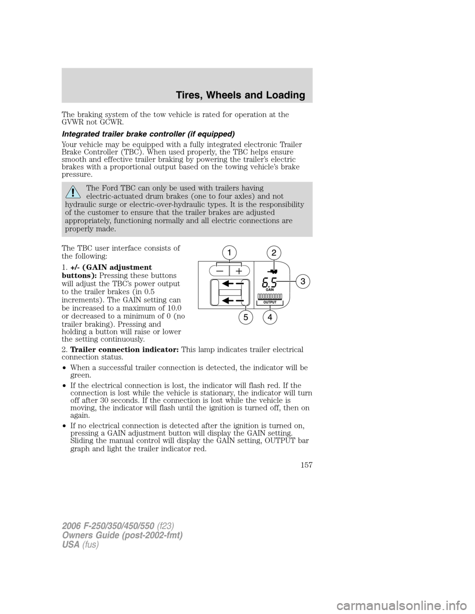
The TBC user interface consists of
the following:
1.+/- (GAIN adjustment
buttons):Pressing these buttons
will adjust the TBC’s power output
to the trailer brakes (in 0.5
increments). The GAIN setting can
be increased to a maximum of 10.0
or decreased to a minimum of 0 (no
trailer braking). Pressing and
holding a button will raise or lower
the setting continuously.
2.Trailer connection indicator:This lamp indicates trailer electrical
connection status.
•When a successful trailer connection is detected, the indicator will be
green.
•If the electrical connection is lost, the indicator will flash red. If the
connection is lost while the vehicle is stationary, the indicator will turn
off after 30 seconds. If the connection is lost while the vehicle is
moving, the indicator will flash until the ignition is turned off, then on
again.
•If no electrical connection is detected after the ignition is turned on,
pressing a GAIN adjustment button will display the GAIN setting.
Sliding the manual control will display the GAIN setting, OUTPUT bar
graph and light the trailer indicator red.
2006 F-250/350/450/550(f23)
Owners Guide (post-2002-fmt)
USA(fus)
Tires, Wheels and Loading
157
Page 159 of 312
5. In a traffic-free environment, tow the trailer on a dry, level surface at
a speed of 20 – 25 mph (30 – 40 km/h) and squeeze the manual control
lever completely.
6. If the trailer wheels lock-up (indicated by squealing tires), reduce the
GAIN setting; if the trailer wheels turn freely, increase the GAIN setting.
Repeat Steps 5 and 6 until the GAIN setting is at a point just below
trailer wheel lock-up. If towing a heavier trailer, trailer wheel lockup may
not be attainable even with the maximum GAIN setting of 10.
Explanation of instrument cluster messages:
The TBC interacts with the instrument cluster message center. These
messages, accompanied by a single chime, will be displayed when the
TBC determines a malfunction in the trailer connection, TBC system, or
in the trailer. These messages are listed below:
TRAILER DISCONNECTED (if equipped with message center) or
CHECK TRAILER (if equipped with mini message center):This
message is displayed when a trailer connection was determined and then
a disconnection, either intentionally or unintentionally, has been sensed
during a given ignition cycle. This message is also displayed during
manual activation without a trailer connected.
TBC FAULT:This message is displayed in response to faults sensed by
the TBC. In the event this message is seen, please take your vehicle to
an authorized dealer for diagnosis and repair. The TBC may still function,
but performance may be degraded.
TRAILER FAULT:The TBC is capable of determining certain faults in
the vehicle wiring and trailer wiring/brake system. These faults do not
mean there is anything wrong with the TBC. This message is displayed
when one of the following faults has occurred:
•
Short circuit on the electric brake output wire:If the TRAILER FAULT
message is displayed with no trailer connected, the problem is with the
vehicle wiring from the TBC to the 7–pin connector in the bumper. If the
message is only displayed with a trailer connected, the problem is related
to the trailer wiring; consult your trailer dealer for assistance.
•Trailer brake overload:The trailer’s brakes are drawing too much
current; consult your trailer dealer for assistance.
Note:Your TBC can be diagnosed by your authorized dealer to determine
exactly which trailer fault has occurred; however, if the fault is with the
trailer this diagnosis isnotcovered under your Ford warranty.
2006 F-250/350/450/550(f23)
Owners Guide (post-2002-fmt)
USA(fus)
Tires, Wheels and Loading
159
Page 160 of 312
Points to Remember:
•Remember to adjust gain setting before using the TBC for the first
time.
•Readjust GAIN setting on the TBC (according to procedure above)
whenever road, weather and trailer or vehicle loading conditions
change from those that existed when the gain was initially set.
•The sliding lever on the TBC should be used only for manual
activation of trailer brakes to assist with proper adjustment of the
GAIN. Misuse, such as application during trailer sway, could cause
instability of trailer and/or tow vehicle.
•Avoid towing in adverse weather conditions. The TBC does not
provide anti-lock control of the trailer wheels. Trailer wheels can
lock-up on slippery surfaces, resulting in reduced stability of trailer
and tow vehicle.
•The TBC interacts with the brake system of the vehicle, including
ABS, in order to reduce the likelihood of trailer wheel lockup.
Therefore, if these systems are not functioning properly the TBC may
not function at full performance.
•When the vehicle is turned off, the TBC Output is disabled and the
display is shut down. Reactivation of the ignition from 3 (OFF) to 4
(ON) will awaken the TBC module.
•The TBC is only a factory or dealer installed item. Ford is not
responsible for warranty or performance of the TBC due to misuse or
customer installation.
Trailer lamps
Trailer lamps are required on most towed vehicles. Make sure all running
lights, brake lights, turn signals and hazard lights are working. See your
authorized dealer or trailer rental agency for proper instructions and
equipment for hooking up trailer lamps.
Using a step bumper (if equipped)
The rear bumper is equipped with an integral hitch and only requires a
ball with a one inch (25.4 mm) shank diameter. The bumper has a 5,000 lb.
(2,270 kg) trailer weight and 500 lb. (227 kg) tongue weight capacity.
If it is necessary to relocate the trailer hitch ball position, a
frame-mounted trailer hitch must be installed.
2006 F-250/350/450/550(f23)
Owners Guide (post-2002-fmt)
USA(fus)
Tires, Wheels and Loading
160
Page 165 of 312
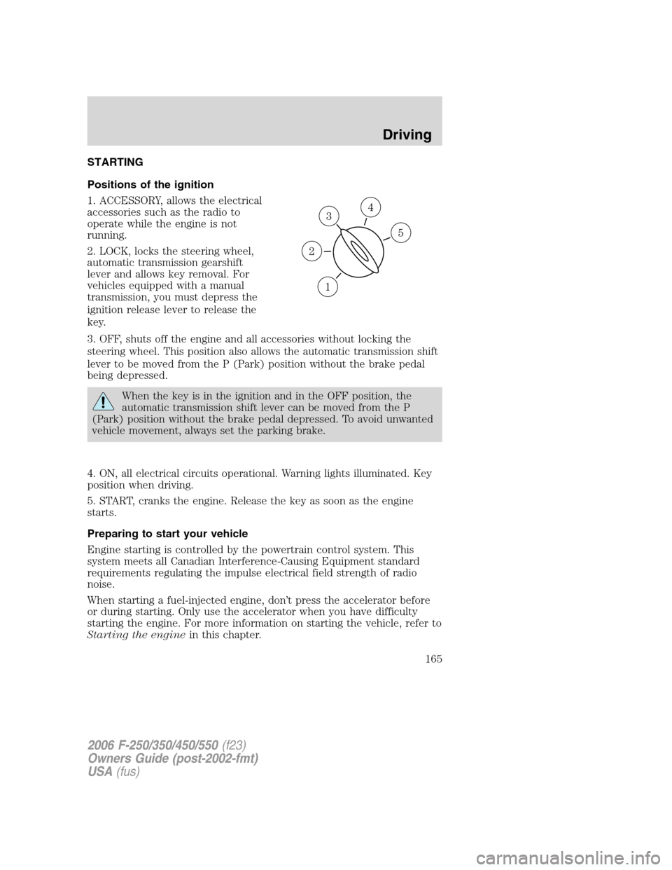
STARTING
Positions of the ignition
1. ACCESSORY, allows the electrical
accessories such as the radio to
operate while the engine is not
running.
2. LOCK, locks the steering wheel,
automatic transmission gearshift
lever and allows key removal. For
vehicles equipped with a manual
transmission, you must depress the
ignition release lever to release the
key.
3. OFF, shuts off the engine and all accessories without locking the
steering wheel. This position also allows the automatic transmission shift
lever to be moved from the P (Park) position without the brake pedal
being depressed.
When the key is in the ignition and in the OFF position, the
automatic transmission shift lever can be moved from the P
(Park) position without the brake pedal depressed. To avoid unwanted
vehicle movement, always set the parking brake.
4. ON, all electrical circuits operational. Warning lights illuminated. Key
position when driving.
5. START, cranks the engine. Release the key as soon as the engine
starts.
Preparing to start your vehicle
Engine starting is controlled by the powertrain control system. This
system meets all Canadian Interference-Causing Equipment standard
requirements regulating the impulse electrical field strength of radio
noise.
When starting a fuel-injected engine, don’t press the accelerator before
or during starting. Only use the accelerator when you have difficulty
starting the engine. For more information on starting the vehicle, refer to
Starting the enginein this chapter.
3
1
2
5
4
2006 F-250/350/450/550(f23)
Owners Guide (post-2002-fmt)
USA(fus)
Driving
165
Page 171 of 312
Four-wheel anti-lock brake system (ABS)
Your vehicle is equipped with an Anti-lock Braking System (ABS). This
system helps you maintain steering control during emergency stops by
keeping the brakes from locking. Noise from the ABS pump motor and
brake pedal pulsation may be observed during ABS braking and the
brake pedal may suddenly travel a little farther as soon as ABS braking is
done and normal brake operation resumes. These are normal
characteristics of the ABS and should be no reason for concern.
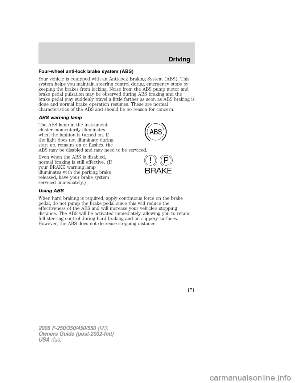
ABS warning lamp
The ABS lamp in the instrument
cluster momentarily illuminates
when the ignition is turned on. If
the light does not illuminate during
start up, remains on or flashes, the
ABS may be disabled and may need to be serviced.
Even when the ABS is disabled,
normal braking is still effective. (If
your BRAKE warning lamp
illuminates with the parking brake
released, have your brake system
serviced immediately.)
Using ABS
When hard braking is required, apply continuous force on the brake
pedal; do not pump the brake pedal since this will reduce the
effectiveness of the ABS and will increase your vehicle’s stopping
distance. The ABS will be activated immediately, allowing you to retain
full steering control during hard braking and on slippery surfaces.
However, the ABS does not decrease stopping distance.
ABS
P!
BRAKE
2006 F-250/350/450/550(f23)
Owners Guide (post-2002-fmt)
USA(fus)
Driving
171
Page 174 of 312
exhibit a slight noise or vibration in tight turns with low vehicle speed.
This is normal behavior and indicates the axle is working.
PREPARING TO DRIVE YOUR VEHICLE
Utility vehicles have a significantly higher rollover rate than
other types of vehicles.
In a rollover crash, an unbelted person is significantly more likely
to die than a person wearing a safety belt.
Your vehicle has larger tires and increased ground clearance, giving the
vehicle a higher center of gravity than a passenger car.
Vehicles with a higher center of gravity such as utility and
four-wheel drive vehicles handle differently than vehicles with a
lower center of gravity. Utility and four-wheel drive vehicles arenot
designed for cornering at speeds as high as passenger cars any more
than low-slung sports cars are designed to perform satisfactorily under
off-road conditions. Avoid sharp turns, excessive speed and abrupt
maneuvers in these vehicles. Failure to drive cautiously could result in
an increased risk of loss of vehicle control, vehicle rollover, personal
injury and death.
Loaded vehicles, with a higher center of gravity, may handle
differently than unloaded vehicles. Extra precautions such as
slower speeds and increased stopping distance should be taken when
driving a heavily loaded vehicle.
AUTOMATIC TRANSMISSION OPERATION (IF EQUIPPED)
Brake-shift interlock
This vehicle is equipped with a brake-shift interlock feature that prevents
the gearshift lever from being moved from P (Park) when the ignition is
in the 4 (ON) position unless brake pedal is depressed.
If you cannot move the gearshift lever out of P (Park) with ignition in
the 4 (ON) position and the brake pedal depressed:
1. Apply the parking brake, turn ignition key to 2 (LOCK), then remove
the key.
2006 F-250/350/450/550(f23)
Owners Guide (post-2002-fmt)
USA(fus)
Driving
174
Page 175 of 312
2. Insert the key and turn it to 3 (OFF).Apply the brake pedal and
shift to N (Neutral).
When the key is in the ignition and in the OFF position, the
automatic transmission shift lever can be moved from the P
(Park) position without the brake pedal depressed. To avoid unwanted
vehicle movement, always set the parking brake.
3. Start the vehicle.
If it is necessary to use the above procedure to move the gearshift lever,
it is possible that a fuse has blown or the vehicle’s brakelamps are not
operating properly. Refer toFuses and relaysin theRoadside
Emergencieschapter.
Do not drive your vehicle until you verify that the brakelamps
are working.
Always set the parking brake fully and make sure the gearshift is
latched in P (Park). Turn the ignition to the LOCK position and
remove the key whenever you leave your vehicle.
If the parking brake is fully released, but the brake warning lamp
remains illuminated, the brakes may not be working properly.
See your authorized dealer as soon as possible.
2006 F-250/350/450/550(f23)
Owners Guide (post-2002-fmt)
USA(fus)
Driving
175