2006 FORD F250 SUPER DUTY fuse
[x] Cancel search: fusePage 2 of 312
Seating and Safety Restraints 90Seating 90
Safety restraints 97
Airbags 108
Child restraints 117
Tires, Wheels and Loading 129Tire Information 132
Tire Inflation 133
Vehicle loading 148
Trailer towing 155
Trailer Brake Controller-Integrated 159
Recreational towing 165
Driving 167Starting 167
Brakes 172
Transmission operation 176
Roadside Emergencies 202Getting roadside assistance 202
Hazard flasher switch 204
Fuel pump shut-off switch 204
Fuses and relays 205
Changing tires 214
Lug Nut Torque 225
Jump starting 226
Wrecker towing 232
Customer Assistance 234Reporting safety defects (U.S. only) 240
Cleaning 241Table of Contents
2
2006 F-250/350/450/550 (f23)
Owners Guide (post-2002-fmt)
USA (fus)
Page 10 of 312
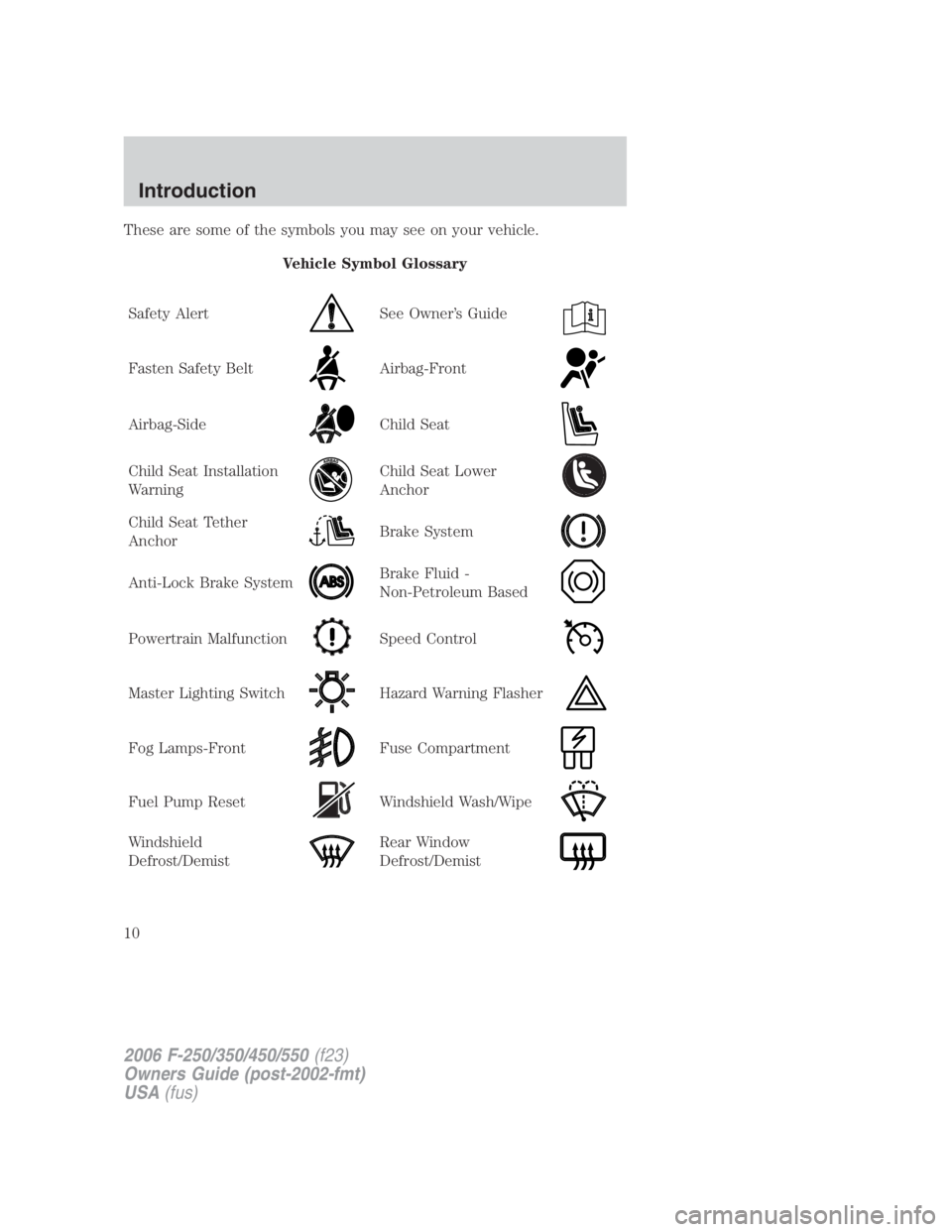
These are some of the symbols you may see on your vehicle.
Vehicle Symbol Glossary
Safety Alert See Owner’s Guide
Fasten Safety Belt Airbag-Front
Airbag-Side Child Seat
Child Seat Installation
Warning Child Seat Lower
Anchor
Child Seat Tether
Anchor Brake System
Anti-Lock Brake System Brake Fluid -
Non-Petroleum Based
Powertrain Malfunction Speed Control
Master Lighting Switch Hazard Warning Flasher
Fog Lamps-Front Fuse Compartment
Fuel Pump Reset Windshield Wash/Wipe
Windshield
Defrost/Demist Rear Window
Defrost/Demist
2006 F-250/350/450/550 (f23)
Owners Guide (post-2002-fmt)
USA (fus)Introduction
10
Page 56 of 312
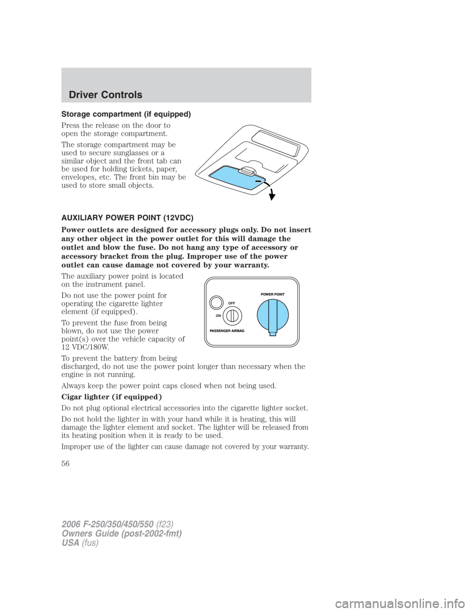
Storage compartment (if equipped)
Press the release on the door to
open the storage compartment.
The storage compartment may be
used to secure sunglasses or a
similar object and the front tab can
be used for holding tickets, paper,
envelopes, etc. The front bin may be
used to store small objects.
AUXILIARY POWER POINT (12VDC)
Power outlets are designed for accessory plugs only. Do not insert
any other object in the power outlet for this will damage the
outlet and blow the fuse. Do not hang any type of accessory or
accessory bracket from the plug. Improper use of the power
outlet can cause damage not covered by your warranty.
The auxiliary power point is located
on the instrument panel.
Do not use the power point for
operating the cigarette lighter
element (if equipped).
To prevent the fuse from being
blown, do not use the power
point(s) over the vehicle capacity of
12 VDC/180W.
To prevent the battery from being
discharged, do not use the power point longer than necessary when the
engine is not running.
Always keep the power point caps closed when not being used.
Cigar lighter (if equipped)
Do not plug optional electrical accessories into the cigarette lighter socket.
Do not hold the lighter in with your hand while it is heating, this will
damage the lighter element and socket. The lighter will be released from
its heating position when it is ready to be used.
Improper use of the lighter can cause damage not covered by your warranty.
2006 F-250/350/450/550 (f23)
Owners Guide (post-2002-fmt)
USA (fus)Driver Controls
56
Page 64 of 312
UPFITTER CONTROLS (IF EQUIPPED)
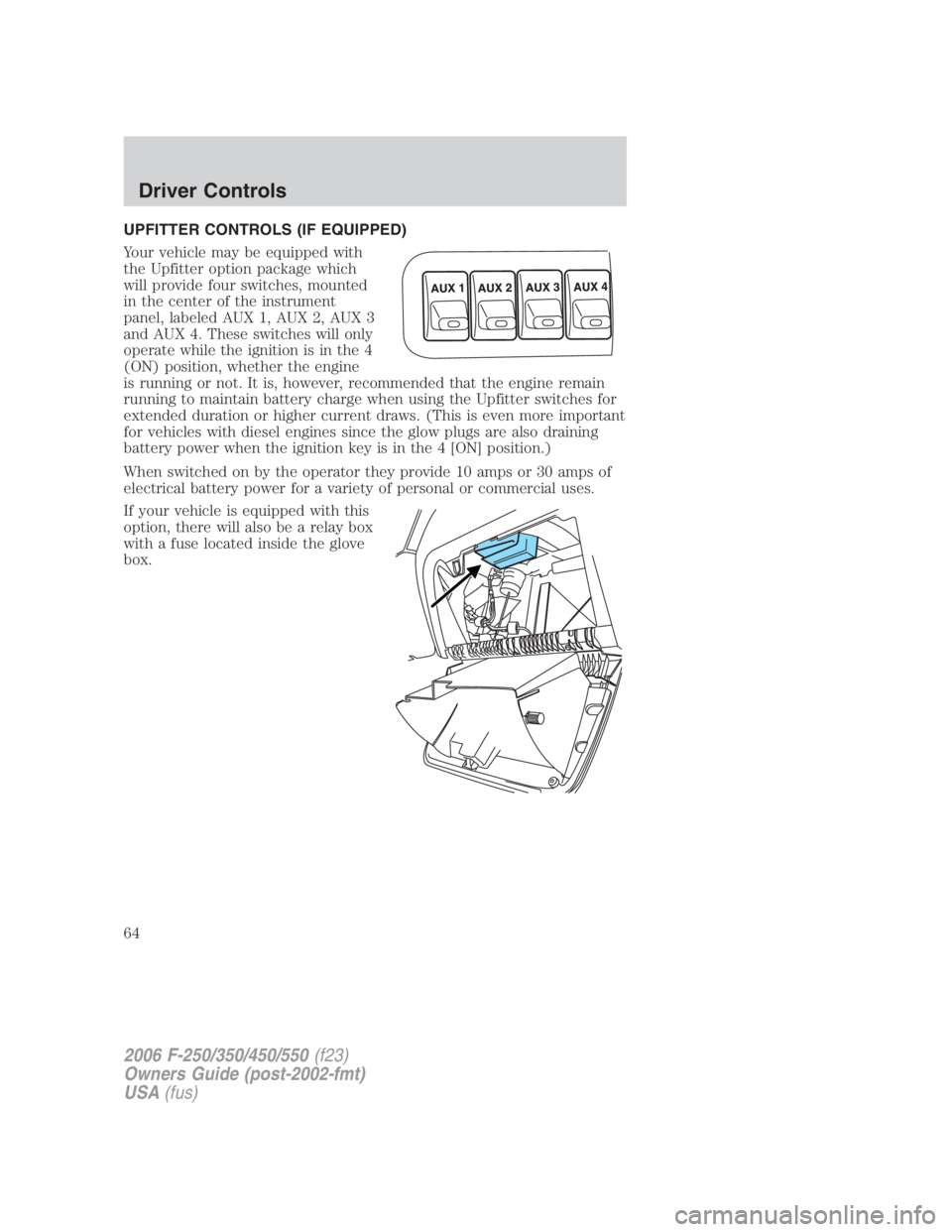
Your vehicle may be equipped with
the Upfitter option package which
will provide four switches, mounted
in the center of the instrument
panel, labeled AUX 1, AUX 2, AUX 3
and AUX 4. These switches will only
operate while the ignition is in the 4
(ON) position, whether the engine
is running or not. It is, however, recommended that the engine remain
running to maintain battery charge when using the Upfitter switches for
extended duration or higher current draws. (This is even more important
for vehicles with diesel engines since the glow plugs are also draining
battery power when the ignition key is in the 4 [ON] position.)
When switched on by the operator they provide 10 amps or 30 amps of
electrical battery power for a variety of personal or commercial uses.
If your vehicle is equipped with this
option, there will also be a relay box
with a fuse located inside the glove
box.
2006 F-250/350/450/550 (f23)
Owners Guide (post-2002-fmt)
USA (fus)Driver Controls
64
Page 65 of 312
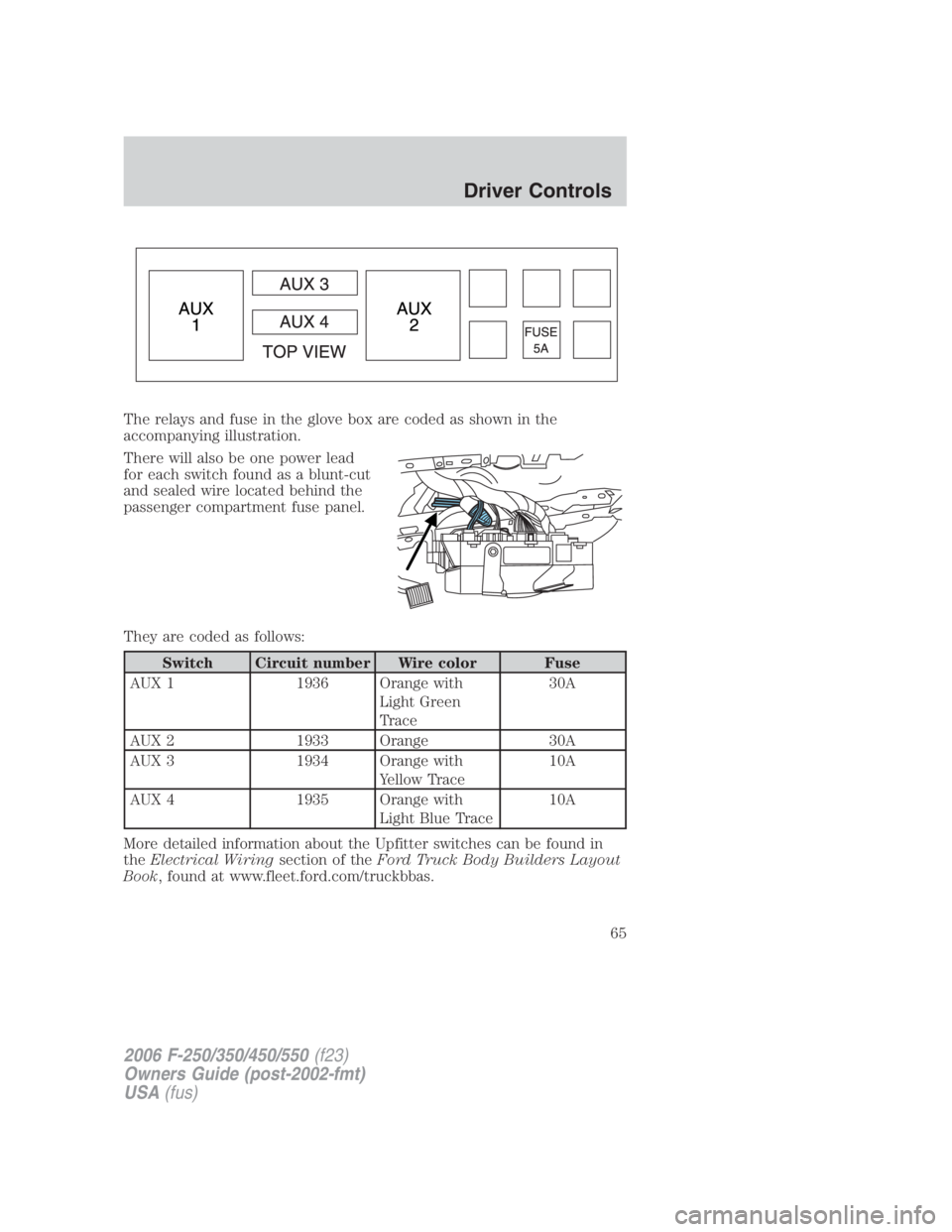
The relays and fuse in the glove box are coded as shown in the
accompanying illustration.
There will also be one power lead
for each switch found as a blunt-cut
and sealed wire located behind the
passenger compartment fuse panel.
They are coded as follows:
Switch Circuit number Wire color Fuse
AUX 1 1936 Orange with
Light Green
Trace 30A
AUX 2 1933 Orange 30A
AUX 3 1934 Orange with
Yellow Trace 10A
AUX 4 1935 Orange with
Light Blue Trace 10A
More detailed information about the Upfitter switches can be found in
the Electrical Wiring section of the Ford Truck Body Builders Layout
Book , found at www.fleet.ford.com/truckbbas.
2006 F-250/350/450/550 (f23)
Owners Guide (post-2002-fmt)
USA (fus) Driver Controls
65
Page 110 of 312
Do not attempt to service, repair, or modify the airbag
supplemental restraint systems or its fuses. See your authorized
dealer.
The front passenger air bag is not designed to offer protection to
an occupant in the center front seating position.
Modifying or adding equipment to the front end of the vehicle
(including frame, bumper, front end body structure and tow
hooks) may affect the performance of the airbag system, increasing the
risk of injury. Do not modify the front end of the vehicle.
Additional equipment such as snowplow equipment may effect
the performance of the airbag sensors increasing the risk of
injury. Please refer to the Body Builders Layout Book for instructions
about the appropriate installation of additional equipment.
Removing the blocker beam without installing snow plow
attachment hardware may effect airbag deployment in a crash.
Do not operate the truck unless either the blocker beam or snow plow
attachment hardware is installed on the vehicle.
Children and airbags
For additional important safety information, read all information on
safety restraints in this guide.
Children must always be properly restrained. Failure to follow these
instructions may increase the risk of injury in a collision.
An infant in a rear-facing seat faces a high risk of serious or fatal
injuries from a deploying passenger airbag. Rear facing infant
seats should NEVER be placed in the front seats, unless the passenger
airbag is turned off. See Passenger airbag ON/OFF switch.
2006 F-250/350/450/550 (f23)
Owners Guide (post-2002-fmt)
USA (fus)Seating and Safety Restraints
110
Page 165 of 312
Backing up
• Practice backing up, particularly if you are a novice. Turn the steering
wheel to the right to move the trailer’s rear end to the right.
• Sharp steering movements may cause the trailer to jackknife or go out
of control.
Tires
• All trailer tires should be of the same size, and construction.
• Select tires that meet the trailer loading requirements.
• Always check tow vehicle and trailer tire pressure before towing.
Launching or retrieving a boat
When backing down a ramp during boat launching or retrieval,
• Do not allow the static water level to rise above the bottom edge of
the rear bumper.
• Do not allow waves to break higher than 6 inches (15 cm) above the
bottom edge of the rear bumper.
• Disconnect the trailer tow electrical connector to prevent blown fuses
caused by water entering into your trailer’s electrical wiring.
Exceeding these limits may allow water to enter critical vehicle
components, adversely affecting driveability, emissions and reliability.
Replace front and rear axle lubricants any time the axles have been
submerged in water. Axle lubricant quantities are not to be checked
unless a leak is suspected.
RECREATIONAL TOWING
This applies to all 4x2 trucks with rear wheel drive capability.
An example of recreational towing is towing your vehicle behind a
motorhome. The following recreational towing guidelines are designed to
ensure that your transmission is not damaged.
• Place the transmission in N (Neutral).
• Maximum speed is 35 mph (56 km/h).
• Maximum distance is 50 miles (80 km).
If a distance of 50 miles (80 km) or a speed of 35 mph (56 km/h) must
be exceeded, you must disconnect the driveshaft. Ford recommends the
driveshaft be removed/installed only by a qualified technician. See your
local authorized dealer for driveshaft removal/installation.
2006 F-250/350/450/550 (f23)
Owners Guide (post-2002-fmt)
USA (fus) Tires, Wheels and Loading
165
Page 176 of 312
Vehicles with a higher center of gravity such as utility and
four-wheel drive vehicles handle differently than vehicles with a
lower center of gravity. Utility and four-wheel drive vehicles are not
designed for cornering at speeds as high as passenger cars any more
than low-slung sports cars are designed to perform satisfactorily under
off-road conditions. Avoid sharp turns, excessive speed and abrupt
maneuvers in these vehicles. Failure to drive cautiously could result in
an increased risk of loss of vehicle control, vehicle rollover, personal
injury and death.
Loaded vehicles, with a higher center of gravity, may handle
differently than unloaded vehicles. Extra precautions such as
slower speeds and increased stopping distance should be taken when
driving a heavily loaded vehicle.
AUTOMATIC TRANSMISSION OPERATION (IF EQUIPPED)
Brake-shift interlock
This vehicle is equipped with a brake-shift interlock feature that prevents
the gearshift lever from being moved from P (Park) when the ignition is
in the 4 (ON) position unless brake pedal is depressed.
If you cannot move the gearshift lever out of P (Park) with ignition in
the 4 (ON) position and the brake pedal depressed:
1. Apply the parking brake, turn ignition key to 2 (LOCK), then remove
the key.
2. Insert the key and turn it to 3 (OFF). Apply the brake pedal and
shift to N (Neutral) .
When the key is in the ignition and in the OFF position, the
automatic transmission shift lever can be moved from the P
(Park) position without the brake pedal depressed. To avoid unwanted
vehicle movement, always set the parking brake.
3. Start the vehicle.
If it is necessary to use the above procedure to move the gearshift lever,
it is possible that a fuse has blown or the vehicle’s brakelamps are not
operating properly. Refer to Fuses and relays in the Roadside
Emergencies chapter.
2006 F-250/350/450/550 (f23)
Owners Guide (post-2002-fmt)
USA (fus)Driving
176