2006 FORD F250 SUPER DUTY battery
[x] Cancel search: batteryPage 84 of 312
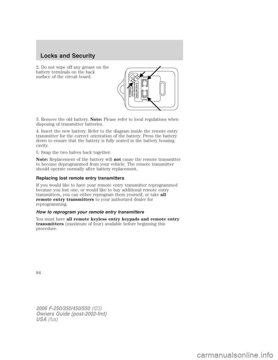
2. Do not wipe off any grease on the
battery terminals on the back
surface of the circuit board.
3. Remove the old battery. Note: Please refer to local regulations when
disposing of transmitter batteries.
4. Insert the new battery. Refer to the diagram inside the remote entry
transmitter for the correct orientation of the battery. Press the battery
down to ensure that the battery is fully seated in the battery housing
cavity.
5. Snap the two halves back together.
Note: Replacement of the battery will not cause the remote transmitter
to become deprogrammed from your vehicle. The remote transmitter
should operate normally after battery replacement.
Replacing lost remote entry transmitters
If you would like to have your remote entry transmitter reprogrammed
because you lost one, or would like to buy additional remote entry
transmitters, you can either reprogram them yourself, or take all
remote entry transmitters to your authorized dealer for
reprogramming.
How to reprogram your remote entry transmitters
You must have all remote keyless entry keypads and remote entry
transmitters (maximum of four) available before beginning this
procedure.
2006 F-250/350/450/550 (f23)
Owners Guide (post-2002-fmt)
USA (fus)Locks and Security
84
Page 86 of 312
Illuminated entry
The interior lamps illuminate when the remote entry system is used to
unlock the door(s).
The illuminated entry system will turn off the interior lights if:
• the ignition switch is turned to the 4 (ON) position, or
• the remote transmitter lock control is pressed, or
• the 7 • 8 and the 9 • 0 controls on the keyless entry keypad are
pressed, or
• after 25 seconds of illumination.
The dome lamp control (if equipped) must not be set to the off position
for the illuminated entry system to operate.
The inside lights will not turn off if:
• they have been turned on with the dimmer control, or
• any door is open.
The battery saver will shut off the interior lamps 30 minutes after the
ignition has been turned to the 3 (OFF) position, 10 minutes after if the
dome lamp is off, and 30 minutes after if the dome lamp switch is left
on.
KEYLESS ENTRY SYSTEM
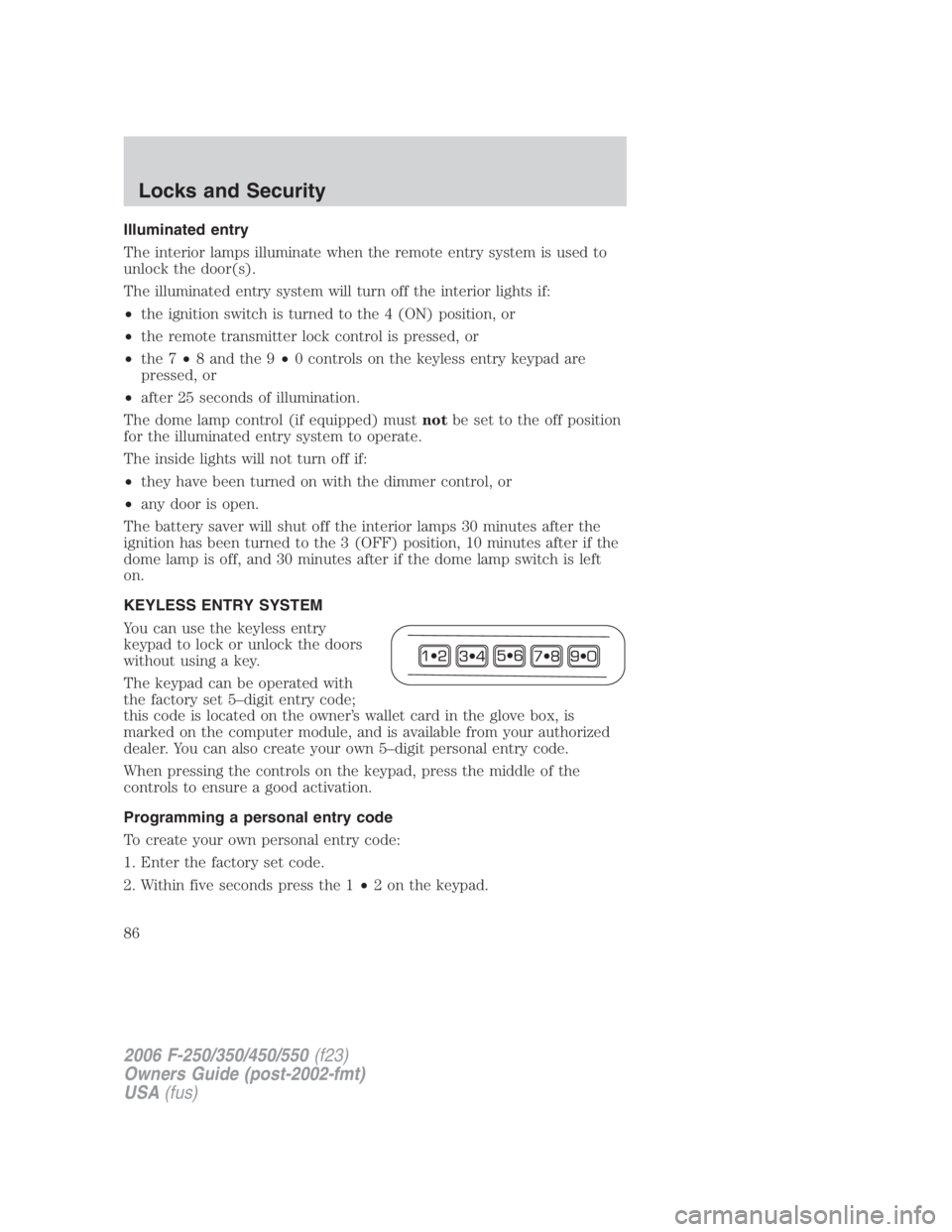
You can use the keyless entry
keypad to lock or unlock the doors
without using a key.
The keypad can be operated with
the factory set 5–digit entry code;
this code is located on the owner’s wallet card in the glove box, is
marked on the computer module, and is available from your authorized
dealer. You can also create your own 5–digit personal entry code.
When pressing the controls on the keypad, press the middle of the
controls to ensure a good activation.
Programming a personal entry code
To create your own personal entry code:
1. Enter the factory set code.
2. Within five seconds press the 1 • 2 on the keypad.
2006 F-250/350/450/550 (f23)
Owners Guide (post-2002-fmt)
USA (fus)Locks and Security
86
Page 161 of 312
5. In a traffic-free environment, tow the trailer on a dry, level surface at
a speed of 20 – 25 mph (30 – 40 km/h) and squeeze the manual control
lever completely.
6. If the trailer wheels lock-up (indicated by squealing tires), reduce the
GAIN setting; if the trailer wheels turn freely, increase the GAIN setting.
Repeat Steps 5 and 6 until the GAIN setting is at a point just below
trailer wheel lock-up. If towing a heavier trailer, trailer wheel lockup may
not be attainable even with the maximum GAIN setting of 10.
Explanation of instrument cluster messages:
The TBC interacts with the instrument cluster message center. These
messages, accompanied by a single chime, will be displayed when the
TBC determines a malfunction in the trailer connection, TBC system, or
in the trailer. These messages are listed below:
TRAILER DISCONNECTED (if equipped with message center) or
CHECK TRAILER (if equipped with mini message center): This
message is displayed when a trailer connection was determined and then
a disconnection, either intentionally or unintentionally, has been sensed
during a given ignition cycle. It is also displayed if a trailer fault occurs
causing the trailer to appear disconnected. This message is also
displayed during manual activation without a trailer connected.
TBC FAULT: This message is displayed in response to faults sensed by
the TBC. In the event this message is seen, please take your vehicle to
an authorized dealer for diagnosis and repair. The TBC may still function,
but performance may be degraded.
TRAILER FAULT: The TBC is capable of determining certain faults in
the vehicle wiring and trailer wiring/brake system. These faults do not
mean there is anything wrong with the TBC. This message is displayed
when one of the following faults has occurred:
• Short circuit on the electric brake output wire: If the TRAILER
FAULT message is displayed with no trailer connected, the problem is
with the vehicle wiring from the TBC to the 7–pin connector in the
bumper. If the message is only displayed with a trailer connected, the
problem is related to the trailer wiring; consult your trailer dealer for
assistance. This can be a short to ground (i.e., chaffed wire) or a short
to voltage (i.e., pulled pin on trailer emergency break-away battery).
• Trailer brake overload: The trailer brakes are drawing too much
current; consult your trailer dealer for assistance.
Note: Your TBC can be diagnosed by your authorized dealer to
determine exactly which trailer fault has occurred; however, if the fault
is with the trailer this diagnosis is not covered under your Ford
warranty.
2006 F-250/350/450/550 (f23)
Owners Guide (post-2002-fmt)
USA (fus) Tires, Wheels and Loading
161
Page 177 of 312
Do not drive your vehicle until you verify that the brakelamps
are working.
Always set the parking brake fully and make sure the gearshift is
latched in P (Park). Turn the ignition to the LOCK position and
remove the key whenever you leave your vehicle.
If the parking brake is fully released, but the brake warning lamp
remains illuminated, the brakes may not be working properly.
See your authorized dealer as soon as possible.
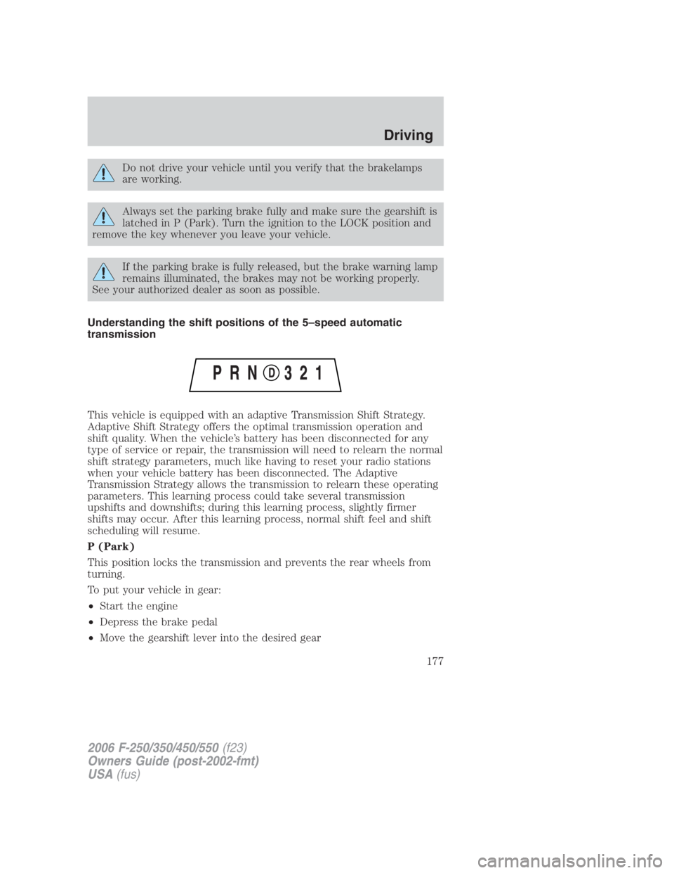
Understanding the shift positions of the 5–speed automatic
transmission
This vehicle is equipped with an adaptive Transmission Shift Strategy.
Adaptive Shift Strategy offers the optimal transmission operation and
shift quality. When the vehicle’s battery has been disconnected for any
type of service or repair, the transmission will need to relearn the normal
shift strategy parameters, much like having to reset your radio stations
when your vehicle battery has been disconnected. The Adaptive
Transmission Strategy allows the transmission to relearn these operating
parameters. This learning process could take several transmission
upshifts and downshifts; during this learning process, slightly firmer
shifts may occur. After this learning process, normal shift feel and shift
scheduling will resume.
P (Park)
This position locks the transmission and prevents the rear wheels from
turning.
To put your vehicle in gear:
• Start the engine
• Depress the brake pedal
• Move the gearshift lever into the desired gear
2006 F-250/350/450/550 (f23)
Owners Guide (post-2002-fmt)
USA (fus) Driving
177
Page 202 of 312
ROADSIDE ASSISTANCE
Getting roadside assistance
To fully assist you should you have a vehicle concern, Ford Motor
Company offers a complimentary roadside assistance program. This
program is separate from the New Vehicle Limited Warranty. The service
is available:
• 24–hours, seven days a week
• for the New Vehicle Limited Warranty period of three years or
36,000 miles (60,000 km), whichever occurs first on Ford and Mercury
vehicles, and four years or 50,000 miles (80,000 km) on Lincoln
vehicles.
Roadside assistance will cover:
• a flat tire change with a good spare (except Ford GT which has a tire
inflation kit)
• battery jump start
• lock-out assistance (key replacement cost is the customer’s
responsibility)
• fuel delivery – Independent Service Contractors, if not prohibited by
state, local or municipal law shall deliver up to 2.0 gallons (7.5L) of
gasoline or 5 gallons (18.9L) of diesel fuel to a disabled vehicle.
• winch out – available within 100 feet (30.5 meters) of a paved or
county maintained road, no recoveries.
• towing – Ford/Mercury/Lincoln eligible vehicle towed to an authorized
dealer within 35 miles (56.3 km) of the disablement location or to the
nearest authorized dealer. If a member requests to be towed to an
authorized dealer more than 35 miles (56.3 km) from the disablement
location, the member shall be responsible for any mileage costs in
excess of 35 miles (56.3 km).
Trailers shall be covered up to $100 if the disabled eligible vehicle
requires service at the nearest authorized dealer. If the trailer is disabled,
but the towing vehicle is operational, the trailer does not qualify for any
roadside services.
2006 F-250/350/450/550 (f23)
Owners Guide (post-2002-fmt)
USA (fus)Roadside Emergencies
202
Page 204 of 312
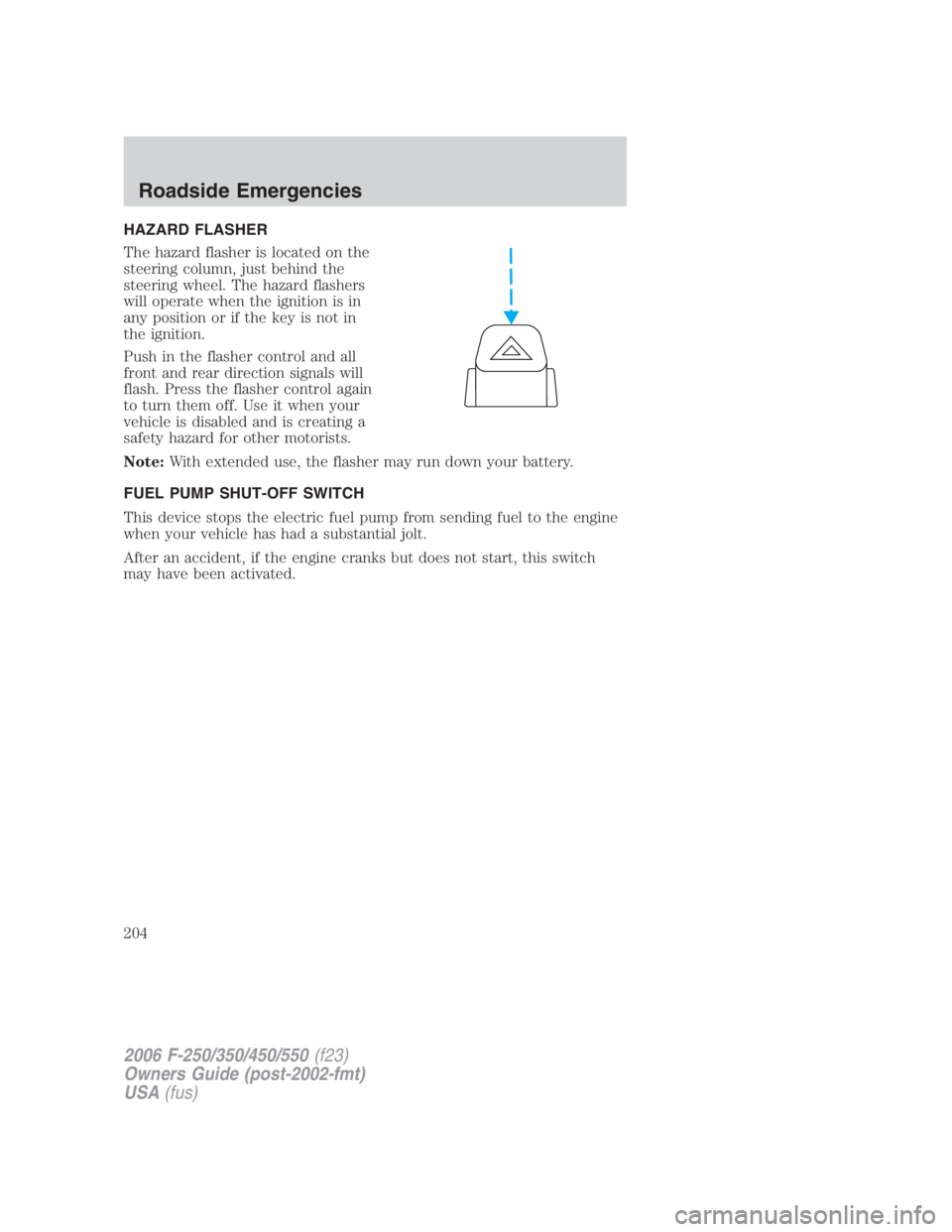
HAZARD FLASHER
The hazard flasher is located on the
steering column, just behind the
steering wheel. The hazard flashers
will operate when the ignition is in
any position or if the key is not in
the ignition.
Push in the flasher control and all
front and rear direction signals will
flash. Press the flasher control again
to turn them off. Use it when your
vehicle is disabled and is creating a
safety hazard for other motorists.
Note: With extended use, the flasher may run down your battery.
FUEL PUMP SHUT-OFF SWITCH
This device stops the electric fuel pump from sending fuel to the engine
when your vehicle has had a substantial jolt.
After an accident, if the engine cranks but does not start, this switch
may have been activated.
2006 F-250/350/450/550 (f23)
Owners Guide (post-2002-fmt)
USA (fus)Roadside Emergencies
204
Page 207 of 312
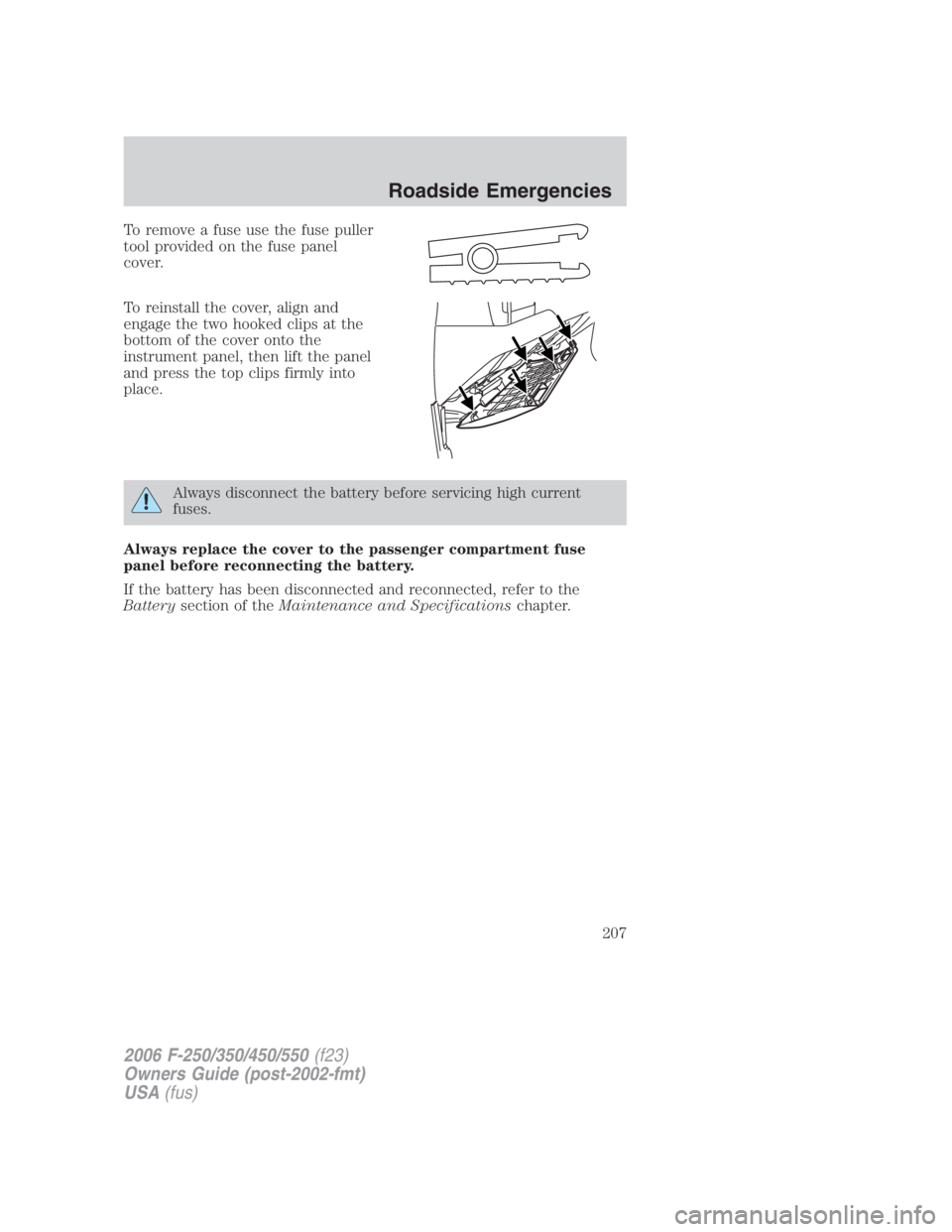
To remove a fuse use the fuse puller
tool provided on the fuse panel
cover.
To reinstall the cover, align and
engage the two hooked clips at the
bottom of the cover onto the
instrument panel, then lift the panel
and press the top clips firmly into
place.
Always disconnect the battery before servicing high current
fuses.
Always replace the cover to the passenger compartment fuse
panel before reconnecting the battery.
If the battery has been disconnected and reconnected, refer to the
Battery section of the Maintenance and Specifications chapter.
2006 F-250/350/450/550 (f23)
Owners Guide (post-2002-fmt)
USA (fus) Roadside Emergencies
207
Page 210 of 312
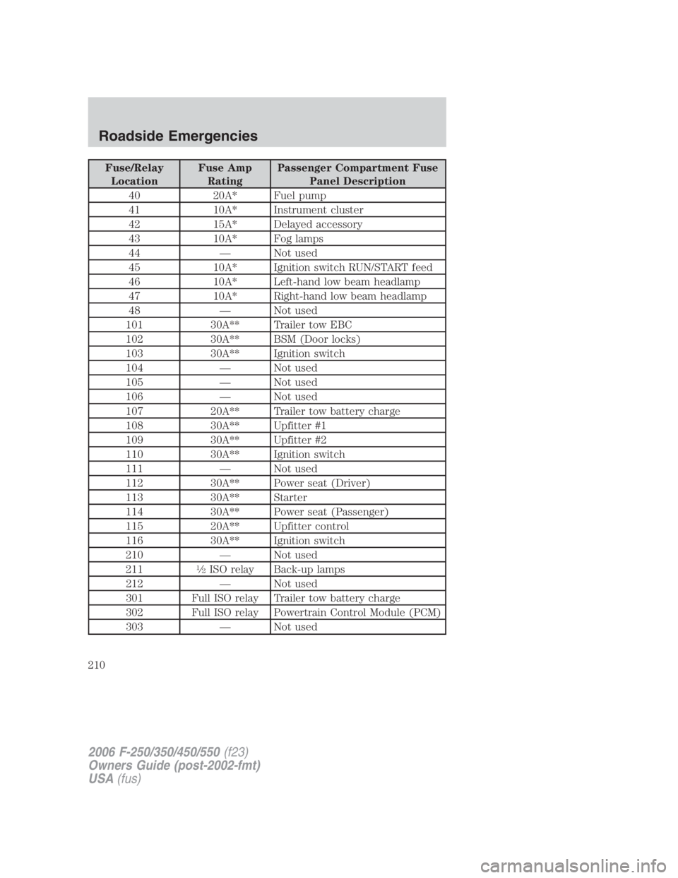
Fuse/Relay
Location Fuse Amp
Rating Passenger Compartment Fuse
Panel Description
40 20A* Fuel pump
41 10A* Instrument cluster
42 15A* Delayed accessory
43 10A* Fog lamps
44 — Not used
45 10A* Ignition switch RUN/START feed
46 10A* Left-hand low beam headlamp
47 10A* Right-hand low beam headlamp
48 — Not used
101 30A** Trailer tow EBC
102 30A** BSM (Door locks)
103 30A** Ignition switch
104 — Not used
105 — Not used
106 — Not used
107 20A** Trailer tow battery charge
108 30A** Upfitter #1
109 30A** Upfitter #2
110 30A** Ignition switch
111 — Not used
112 30A** Power seat (Driver)
113 30A** Starter
114 30A** Power seat (Passenger)
115 20A** Upfitter control
116 30A** Ignition switch
210 — Not used
211 1
� 2
ISO relay Back-up lamps
212 — Not used
301 Full ISO relay Trailer tow battery charge
302 Full ISO relay Powertrain Control Module (PCM)
303 — Not used
2006 F-250/350/450/550 (f23)
Owners Guide (post-2002-fmt)
USA (fus)Roadside Emergencies
210