2006 BMW 525I instrument cluster
[x] Cancel search: instrument clusterPage 66 of 248
Controls
65Reference
At a glance
Driving tips
Communications
Navigation
Entertainment
Mobility
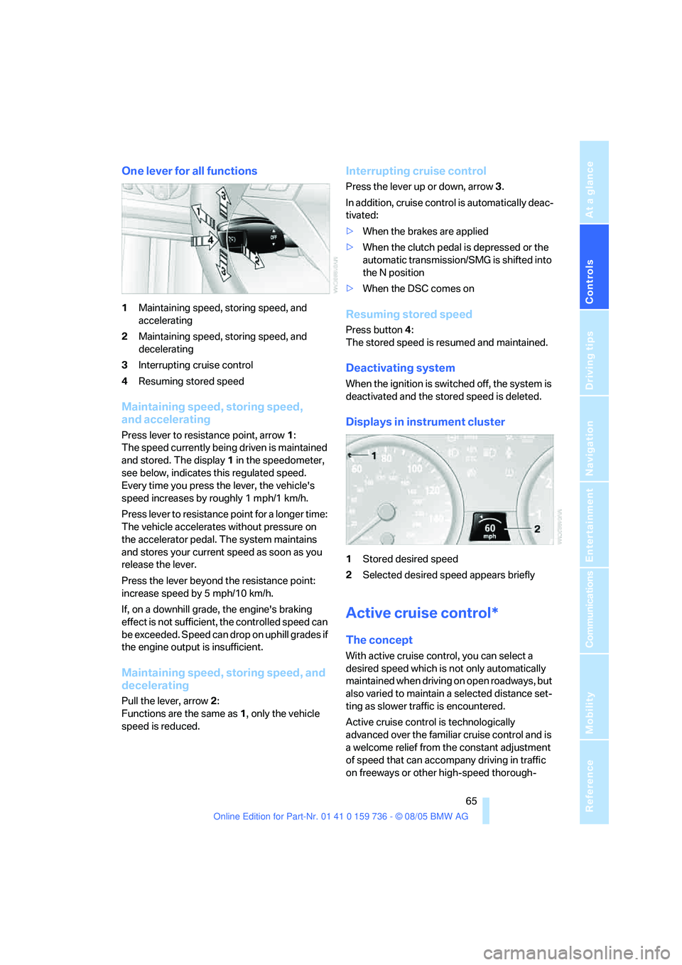
One lever for all functions
1Maintaining speed, storing speed, and
accelerating
2Maintaining speed, storing speed, and
decelerating
3Interrupting cruise control
4Resuming stored speed
Maintaining speed, storing speed,
and accelerating
Press lever to resistance point, arrow 1:
The speed currently being driven is maintained
and stored. The display1 in the speedometer,
see below, indicates this regulated speed.
Every time you press the lever, the vehicle's
speed increases by roughly 1 mph/1 km/h.
Press lever to resistance point for a longer time:
The vehicle accelerates without pressure on
the accelerator pedal. The system maintains
and stores your current speed as soon as you
release the lever.
Press the lever beyond the resistance point:
increase speed by 5 mph/10 km/h.
If, on a downhill grade, the engine's braking
effect is not sufficient, the controlled speed can
be exceeded. Speed can drop on uphill grades if
the engine output is insufficient.
Maintaining speed, storing speed, and
decelerating
Pull the lever, arrow2:
Functions are the same as1, only the vehicle
speed is reduced.
Interrupting cruise control
Press the lever up or down, arrow3.
In addition, cruise control is automatically deac-
tivated:
>When the brakes are applied
>When the clutch pedal is depressed or the
automatic transmission/SMG is shifted into
the N position
>When the DSC comes on
Resuming stored speed
Press button4:
The stored speed is resumed and maintained.
Deactivating system
When the ignition is switched off, the system is
deactivated and the stored speed is deleted.
Displays in instrument cluster
1Stored desired speed
2Selected desired speed appears briefly
Active cruise control*
The concept
With active cruise control, you can select a
desired speed which is not only automatically
maintained when driving on open roadways, but
also varied to maintain a selected distance set-
ting as slower traffic is encountered.
Active cruise control is technologically
advanced over the familiar cruise control and is
a welcome relief from the constant adjustment
of speed that can accompany driving in traffic
on freeways or other high-speed thorough-
Page 68 of 248
Controls
67Reference
At a glance
Driving tips
Communications
Navigation
Entertainment
Mobility
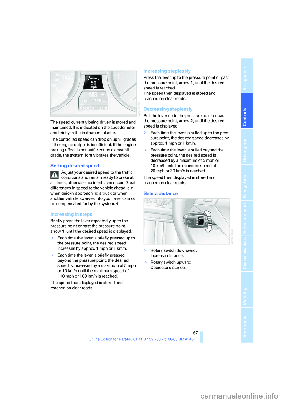
The speed currently being driven is stored and
maintained. It is indicated on the speedometer
and briefly in the instrument cluster.
The controlled speed can drop on uphill grades
if the engine output is insufficient. If the engine
braking effect is not sufficient on a downhill
grade, the system lightly brakes the vehicle.
Setting desired speed
Adjust your desired speed to the traffic
conditions and remain ready to brake at
all times, otherwise accidents can occur. Great
differences in speed to the vehicle ahead, e. g.
when quickly approaching a truck or when
another vehicle swerves into your lane, cannot
be compensated for by the system.<
Increasing in steps
Briefly press the lever repeatedly up to the
pressure point or past the pressure point,
arrow1, until the desired speed is displayed.
>Each time the lever is briefly pressed up to
the pressure point, the desired speed
increases by approx. 1 mph or 1 km/h.
>Each time the lever is briefly pressed
beyond the pressure point, the desired
speed is increased by a maximum of 5 mph
or 10 km/h until the maximum speed of
110mph or 180km/h is reached.
The speed then displayed is stored and
reached on clear roads.
Increasing steplessly
Press the lever up to the pressure point or past
the pressure point, arrow1, until the desired
speed is reached.
The speed then displayed is stored and
reached on clear roads.
Decreasing steplessly
Pull the lever up to the pressure point or past
the pressure point, arrow2, until the desired
speed is displayed.
>Each time the lever is pulled up to the pres-
sure point, the desired speed decreases by
approx. 1 mph or 1 km/h.
>Each time the lever is pulled beyond the
pressure point, the desired speed is
decreased by a maximum of 5 mph or
10 km/h until the minimum speed of
20 mph or 30 km/h is reached.
The speed then displayed is stored and
reached on clear roads.
Select distance
>Rotary switch downward:
Increase distance.
>Rotary switch upward:
Decrease distance.
Page 69 of 248
Driving
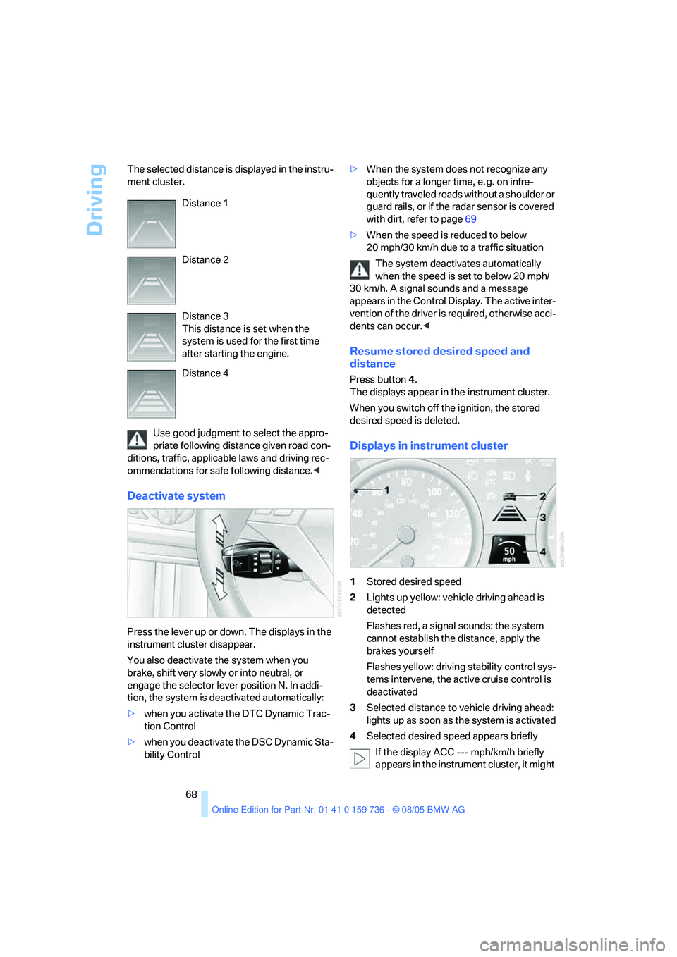
68 The selected distance is displayed in the instru-
ment cluster.
Use good judgment to select the appro-
priate following distance given road con-
ditions, traffic, applicable laws and driving rec-
ommendations for safe following distance.<
Deactivate system
Press the lever up or down. The displays in the
instrument cluster disappear.
You also deactivate the system when you
brake, shift very slowly or into neutral, or
engage the selector lever position N. In addi-
tion, the system is deactivated automatically:
>when you activate the DTC Dynamic Trac-
tion Control
>when you deactivate the DSC Dynamic Sta-
bility Control>When the system does not recognize any
objects for a longer time, e. g. on infre-
quently traveled roads without a shoulder or
guard rails, or if the radar sensor is covered
with dirt, refer to page69
>When the speed is reduced to below
20 mph/30 km/h due to a traffic situation
The system deactivates automatically
when the speed is set to below 20 mph/
30 km/h. A signal sounds and a message
appears in the Control Display. The active inter-
vention of the driver is required, otherwise acci-
dents can occur.<
Resume stored desired speed and
distance
Press button 4.
The displays appear in the instrument cluster.
When you switch off the ignition, the stored
desired speed is deleted.
Displays in instrument cluster
1Stored desired speed
2Lights up yellow: vehicle driving ahead is
detected
Flashes red, a signal sounds: the system
cannot establish the distance, apply the
brakes yourself
Flashes yellow: driving stability control sys-
tems intervene, the active cruise control is
deactivated
3Selected distance to vehicle driving ahead:
lights up as soon as the system is activated
4Selected desired speed appears briefly
If the display ACC --- mph/km/h briefly
appears in the instrument cluster, it might Distance 1
Distance 2
Distance 3
This distance is set when the
system is used for the first time
after starting the engine.
Distance 4
Page 74 of 248
Controls
73Reference
At a glance
Driving tips
Communications
Navigation
Entertainment
Mobility
Energy Control
Displays the current fuel consumption. This
allows you to see whether your current driving
style is conducive to fuel economy with mini-
mum exhaust emissions.
Fuel gauge
Fuel tank capacity: approx. 18.5 gallons/
70 liters. You will find information on refueling
on page186.
If the tilt of the vehicle varies for a longer period,
when you are driving in mountainous areas, for
example, the indicator may fluctuate slightly.
Reserve
After the reserve quantity has been reached, a
message appears for a short time on the Con-
trol Display; the remaining range is shown in the
onboard computer. Below a range of approx.
30 miles/50 km, the message remains on the
Control Display.
Refuel as soon as possible once your
cruising range falls below 30 miles/
50 km, otherwise engine functions are not
ensured and damage can occur.<
Computer
Displays in instrument cluster
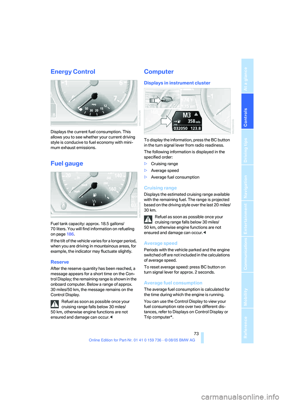
To display the information, press the BC button
in the turn signal lever from radio readiness.
The following information is displayed in the
specified order:
>Cruising range
>Average speed
>Average fuel consumption
Cruising range
Displays the estimated cruising range available
with the remaining fuel. The range is projected
based on the driving style over the last 20 miles/
30 km.
Refuel as soon as possible once your
cruising range falls below 30 miles/
50 km, otherwise engine functions are not
ensured and damage can occur.<
Average speed
Periods with the vehicle parked and the engine
switched off are not included in the calculations
of average speed.
To reset average speed: press BC button on
turn signal lever for approx. 2 seconds.
Average fuel consumption
The average fuel consumption is calculated for
the time during which the engine is running.
You can use the Control Display to view your
fuel consumption rate over two different dis-
tances, refer to Displays on Control Display or
Trip computer*.
Page 78 of 248
Controls
77Reference
At a glance
Driving tips
Communications
Navigation
Entertainment
Mobility
9.Press the controller to apply the setting.
The year is highlighted.
10.Turn the controller to make the adjustment.
11.Press the controller to apply the setting.
The date entry is stored.
To exit the menu:
Select the arrow and press the controller.
Check Control
The concept
The Check Control monitors functions in the
vehicle and issues a message if there is a mal-
function in the monitored systems. This kind of
Check Control message consists of indicator
and warning lamps in the instrument cluster,
and if necessary an acoustic signal and text
messages at the bottom of the Control Display.
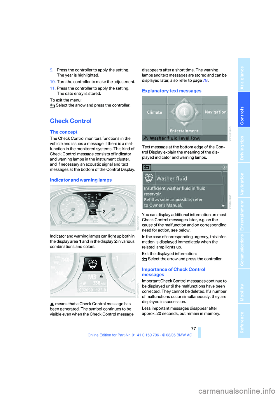
Indicator and warning lamps
Indicator and warning lamps can light up both in
the display area1 and in the display2 in various
combinations and colors.
means that a Check Control message has
been generated. The symbol continues to be
visible even when the Check Control message disappears after a short time. The warning
lamps and text messages are stored and can be
displayed later, also refer to page78.
Explanatory text messages
Text message at the bottom edge of the Con-
trol Display explain the meaning of the dis-
played indicator and warning lamps.
You can display additional information on most
Check Control messages later, e.g. on the
cause of the malfunction and on corresponding
need for action, see below.
In the case of corresponding urgency, this infor-
mation is displayed immediately when the
related lamp lights up.
Exit the displayed information:
Select the arrow and press the controller.
Importance of Check Control
messages
Important Check Control messages continue to
be displayed until the malfunctions have been
corrected. They cannot be deleted. If a number
of malfunctions occur simultaneously, they are
displayed in succession.
Less important messages disappear after
approx. 20 seconds, but remain in memory.
Page 86 of 248
Controls
85Reference
At a glance
Driving tips
Communications
Navigation
Entertainment
Mobility
The laws of physics cannot be repealed,
even with DSC. An appropriate driving
style always remains the responsibility of the
driver. Therefore, do not reduce the additional
safety margin again by taking risks.<
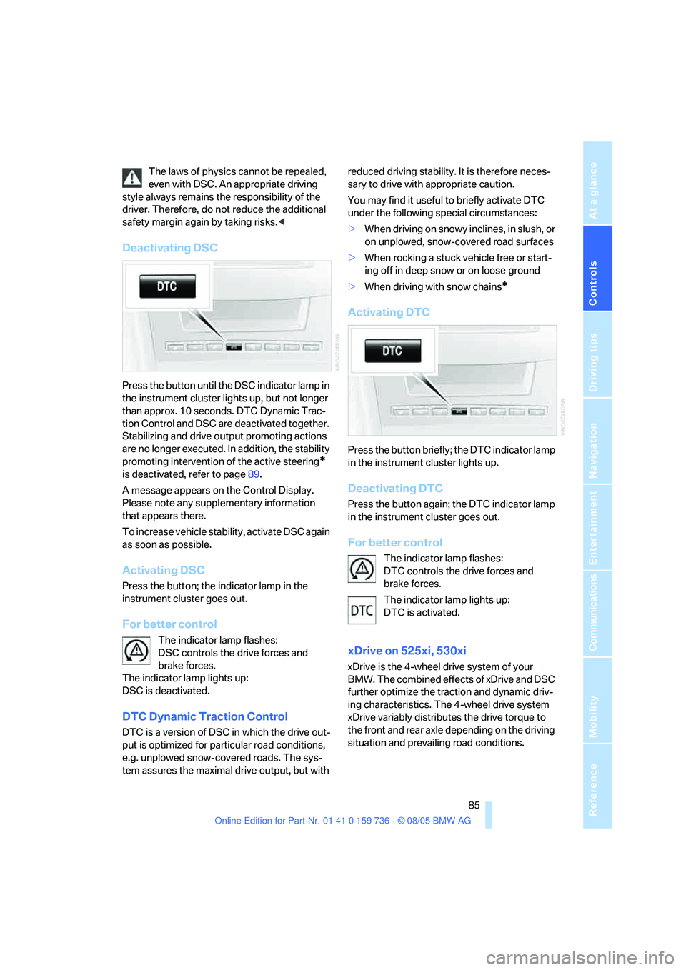
Deactivating DSC
Press the button until the DSC indicator lamp in
the instrument cluster lights up, but not longer
than approx. 10 seconds. DTC Dynamic Trac-
tion Control and DSC are deactivated together.
Stabilizing and drive output promoting actions
are no longer executed. In addition, the stability
promoting intervention of the active steering
*
is deactivated, refer to page89.
A message appears on the Control Display.
Please note any supplementary information
that appears there.
To increase vehicle stability, activate DSC again
as soon as possible.
Activating DSC
Press the button; the indicator lamp in the
instrument cluster goes out.
For better control
The indicator lamp flashes:
DSC controls the drive forces and
brake forces.
The indicator lamp lights up:
DSC is deactivated.
DTC Dynamic Traction Control
DTC is a version of DSC in which the drive out-
put is optimized for particular road conditions,
e.g. unplowed snow-covered roads. The sys-
tem assures the maximal drive output, but with reduced driving stability. It is therefore neces-
sary to drive with appropriate caution.
You may find it useful to briefly activate DTC
under the following special circumstances:
>When driving on snowy inclines, in slush, or
on unplowed, snow-covered road surfaces
>When rocking a stuck vehicle free or start-
ing off in deep snow or on loose ground
>When driving with snow chains
*
Activating DTC
Press the button briefly; the DTC indicator lamp
in the instrument cluster lights up.
Deactivating DTC
Press the button again; the DTC indicator lamp
in the instrument cluster goes out.
For better control
The indicator lamp flashes:
DTC controls the drive forces and
brake forces.
The indicator lamp lights up:
DTC is activated.
xDrive on 525xi, 530xi
xDrive is the 4-wheel drive system of your
BMW. The combined effects of xDrive and DSC
further optimize the traction and dynamic driv-
ing characteristics. The 4-wheel drive system
xDrive variably distributes the drive torque to
the front and rear axle depending on the driving
situation and prevailing road conditions.
Page 87 of 248
Technology for comfort, convenience and safety
86
HDC Hill Descent Control on 525xi,
530xi
The concept
HDC is a system for driving downhill in steep
terrain. This system reduces vehicle speed on
steep downhill gradients, thus allowing you to
maintain even better control of your BMW
under these conditions. The vehicle moves at
approximately twice walking speed without
active intervention from the driver.
HDC is available for activation at vehicle speeds
below approx. 22 mph/35 km/h. When driving
down steep hills with a speed below approx.
22 mph/35 km/h, the vehicle reduces speed
automatically down to approximately double
walking speed, approx. 7 mph/12 km/h, and
then maintains this speed at a constant.
You can use the accelerator or brakes to vary
this automatically controlled speed within a
range extending from approx. 3 mph/5 km/h to
15 mph/25 km/h.
You can specify a target speed within the same
range by using the lever of the cruise control.
Activating HDC
You can activate HDC:
>with the programmable buttons on the
steering wheel, refer to page51
>or via iDrive
iDrive, for principle details, refer to page16.
1.Open the start menu.
2.Press the controller to open the menu.
3.Select "Vehicle settings" and press the
controller.
4.Select "HDC" and press the controller.5.Select "HDC on" and press the controller.
The HDC display in the instrument cluster
appears.
If the vehicle is automatically braked, a message
appears on the Control Display for approx.
20 seconds.
Deactivating HDC
When you use the programmable buttons on
the steering wheel or via iDrive, the HDC display
goes out.
Over approx. 37 mph/60 km/h HDC is immedi-
ately deactivated, and after approx. 10 seconds
when the ignition is switched off.
Using HDC
Manual transmission:
Use HDC in low gears and reverse gear.
Automatic transmission:
You can use HDC in every drive position.
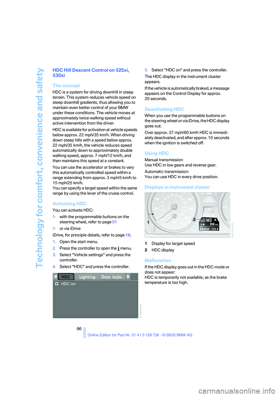
Displays in instrument cluster
1Display for target speed
2HDC display
Malfunction
If the HDC display goes out in the HDC mode or
does not appear:
HDC is temporarily not available, as the brake
temperature is too high.
Page 97 of 248
Lamps
96
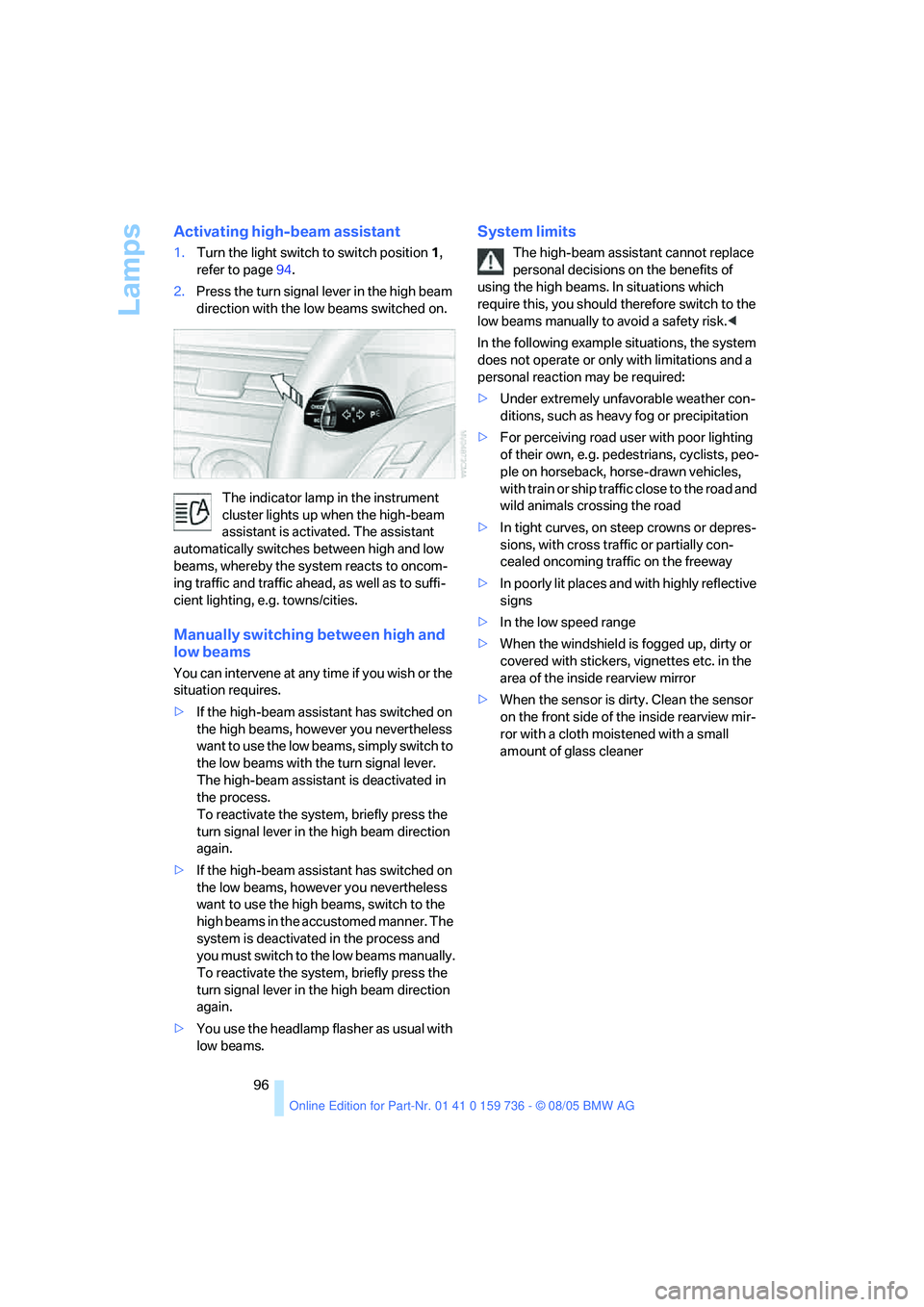
Activating high-beam assistant
1.Turn the light switch to switch position1,
refer to page94.
2.Press the turn signal lever in the high beam
direction with the low beams switched on.
The indicator lamp in the instrument
cluster lights up when the high-beam
assistant is activated. The assistant
automatically switches between high and low
beams, whereby the system reacts to oncom-
ing traffic and traffic ahead, as well as to suffi-
cient lighting, e.g. towns/cities.
Manually switching between high and
low beams
You can intervene at any time if you wish or the
situation requires.
>If the high-beam assistant has switched on
the high beams, however you nevertheless
want to use the low beams, simply switch to
the low beams with the turn signal lever.
The high-beam assistant is deactivated in
the process.
To reactivate the system, briefly press the
turn signal lever in the high beam direction
again.
>If the high-beam assistant has switched on
the low beams, however you nevertheless
want to use the high beams, switch to the
high beams in the accustomed manner. The
system is deactivated in the process and
you must switch to the low beams manually.
To reactivate the system, briefly press the
turn signal lever in the high beam direction
again.
>You use the headlamp flasher as usual with
low beams.
System limits
The high-beam assistant cannot replace
personal decisions on the benefits of
using the high beams. In situations which
require this, you should therefore switch to the
low beams manually to avoid a safety risk.<
In the following example situations, the system
does not operate or only with limitations and a
personal reaction may be required:
>Under extremely unfavorable weather con-
ditions, such as heavy fog or precipitation
>For perceiving road user with poor lighting
of their own, e.g. pedestrians, cyclists, peo-
ple on horseback, horse-drawn vehicles,
with train or ship traffic close to the road and
wild animals crossing the road
>In tight curves, on steep crowns or depres-
sions, with cross traffic or partially con-
cealed oncoming traffic on the freeway
>In poorly lit places and with highly reflective
signs
>In the low speed range
>When the windshield is fogged up, dirty or
covered with stickers, vignettes etc. in the
area of the inside rearview mirror
>When the sensor is dirty. Clean the sensor
on the front side of the inside rearview mir-
ror with a cloth moistened with a small
amount of glass cleaner