Page 215 of 2893

�(�#�'�������������������������������
�/�����)����
Engine Mechanical
Engine Block
........................................................................................................
................................................................. .....................
.....................
.......................................................... .................................
................................................. .......................................
.................................................. ........
............................................
........................................................ .................................
................................................
......................................................
................................................... ..............................................
................................................................
........................................
................................................................. .....................
.....................
.......................................................... .................................
................................................. .......................................
.................................................. ........
............................................
........................................................ .................................
................................................
......................................................
................................................... ..............................................
Special Tools
. 7-2
Component Location Index . 7-3
Connecting Rod and Crankshaft End Play Inspection . 7-5
Crankshaft Main Bearing Replacement . 7-6
Connecting Rod Bearing Replacement . 7-8
Oil Pan Removal . 7-11
Crankshaft and Piston Removal . 7-13
Crankshaft Inspection . 7-15
Block and Piston Inspection . 7-16
Cylinder Bore Honing . 7-18
Piston, Pin, and Connecting Rod Replacement . 7-18
Piston Ring Replacement . 7-21
Piston Installation . 7-23
Connecting Rod Bolt Inspection . 7-25
Crankshaft Installation . 7-25
Oil Pan Installation . 7-29
Transmission End Crankshaft Oil Seal Installation - In Car . 7-32
Sealing Bolt Installation . 7-33
08/08/21 14:32:25 61SNR030_070_0001
ProCarManuals.com
DYNOMITE -2009-
Page 217 of 2893
����
�(�#�'�����������
���������������������������)����
7-3
Component Location Index
MAIN BEARINGSDOWEL PINS LOWER BLOCK
BAFFLE PLATE
CRANKSHAFT CRANKSHAFT OIL SEAL,
TRANSMISSION END
BAFFLE PLATE
DRIVE PLATE (A/T model)
THRUST WASHERS FLYWHEEL (M/T model)
(cont’d)
Oil Clearance Inspection,
page 7-6
Selection, page 7-7
End Play Inspection, page 7-5
Removal, page 7-13
Inspection, page 7-15
Installation, page 7-25
Installation, step 24 on page 7-27
Installation - in Car, page 7-32
08/08/21 14:32:28 61SNR030_070_0003
ProCarManuals.com
DYNOMITE -2009-
Page 221 of 2893
��������
����
Main Bearing Selection
Crankshaft Bore Code Location
Main Journal Code Location
7-7
No. 1 JOURNAL
(PULLEY END)
No. 5 JOURNAL
(TRANSMISSION END)
No. 1 JOURNAL No. 5 JOURNAL
1. Numbers, letters or bars have been stamped on theend of the engine block as a code for the size of
each of the five main journal bores. Write down the
crank bore codes.
If you cannot read the codes because of
accumulated dirt and dust, do not scrub them with
a wire brush or scraper. Clean them only with
solvent or detergent. 2. The main journal codes are stamped on the
crankshaft in either location.
(cont’d)
08/08/21 14:32:32 61SNR030_070_0007
ProCarManuals.com
DYNOMITE -2009-
Page 225 of 2893

���
����
�(�#�'�����������
�������������������
� �����)����
7-11
Oil Pan Removal
1. If the engine is already out of the vehicle, go to step 18.
2. Raise the vehicle on the lift.
3. Drain the engine oil (see page 8-10).
4. Remove the front wheels.
5. Remove the splash shield (see step 25 on page 5-5).
6. Separate the stabilizer links (see page 18-25).
7. Separate the knuckles from the lower arms (see step 6 on page 18-21).
8. Remove the steering gearbox bracket. Remove the steering gearbox mounting bolt, the stiffener
mounting bolt, and the stiffener (see step 36 on
page 5-6).
9. Remove the steering gearbox mounting bolt, the stiffener mounting bolt, and the stiffener. Remove
the harness clamp from the front subframe (see
step 38 on page 5-6).
10. A/T model: Remove the bolt securing the automatic transmission fluid (ATF) filter.
11. Install the front leg assembly, the hook, and the wing nut to an A and Reds engine support hanger
(AAR-T1256) onto the 2006 Civic engine hanger
(VSB02C000025). Carefully position the engine
hanger on the vehicle, and attach the hook to the
slotted hole in the support eyelet. Tighten the wing
nut by hand to lift and support the engine/
transmission (see step 47 on page 5-8). 12. Remove the lower torque rod (see step 49 on page
5-8).
13. M/T model: Remove the front mount mounting bolt (see step 50 on page 5-9).
14. Make the appropriate reference line at both sides of the front subframe that line up with the edges on
the body (see step 51 on page 5-9).
15. Loosen the mid-stiffener mounting bolts on both sides(seestep52onpage5-9).
16. Attach the front subframe adapter (VSB02C000016) to the front subframe, and hang the belt of the front
subframe adapter over the front of the subframe.
Secure the belt with its stop, then tighten the wing
nut (see step 53 on page 5-9).
17. Remove the front subframe (see step 55 on page 5-10).
18. Remove the lower torque rod bracket.
(cont’d)
08/08/21 14:32:34 61SNR030_070_0011
ProCarManuals.com
DYNOMITE -2009-
Page 226 of 2893
����
�������
����
7-12Engine Block
Oil Pan Removal (cont’d)
B
A
19. A/T model: Remove the shift cable cover.
20. K20Z2 engine: Remove the torque converter cover/clutch cover. 21. K20Z3 engine: Remove the clutch cover (A) and the
transmission mounting bolts (B).
22. Remove the bolts securing the oil pan.
23. Using a flat blade screwdriver, separate the oil pan from the lower block in the places shown.
24. Remove the oil pan.
08/08/21 14:32:35 61SNR030_070_0012
ProCarManuals.com
DYNOMITE -2009-
Page 227 of 2893
���
����
����
�(�#�'�����������
�����
��������������� �����)����
7-13
Crankshaft and Piston Removal
1. Remove the engine/transmission (see page 5-3).
2. Remove the transmission: Manual transmission (see page 13-7)
Automatic transmission (see page 14-233)
3. M/T model: Remove the pressure plate (see page 12-19), the clutch disc (see page 12-20), and the
flywheel (see page 12-21).
4. A/T model: Remove the drive plate (see page 14-242).
5. Remove the oil pan (see page 7-11).
6. Remove the oil pump (see page 8-16).
7. Remove the cylinder head (see page 6-38).
8. Remove the baffle plates. 9. Remove the 8 mm bolts in sequence.
10. Remove the bearing cap bolts. To prevent warpage, loosen the bolts in sequence 1/3 turn at a time;
repeat the sequence until all bolts are loosened.
(cont’d)
08/08/21 14:32:35 61SNR030_070_0013
ProCarManuals.com
DYNOMITE -2009-
Page 244 of 2893

����
�
���µ�µ
�µ
�µ
Oil Seal Installed Height: 0.2 1.2 mm
(0.001 0.047 in.)
7-28Engine Block
Crankshaft Installation (cont’d)
0.2 1.2 mm
(0.001 0.047 in.)
BA
6x1.0mm
12 N·m
(1.2 kgf·m, 8.7 lbf·ft)
25. Measure the distance between the engine block (A) and the crankshaft oil seal (B).
26. Install the baffle plates. 27. Install the oil pump (see page 8-21).
28. Install the oil pan (see page 7-29).
29. Install the cylinder head (see page 6-62).
30. M/T model: Install the flywheel (see page 12-21),
the clutch disc (see page 12-23), and the pressure
plate (see page 12-23).
31. A/T model: Install the drive plate (see page 14-242).
32. Install the transmission: Manual transmission (see page 13-14)
Automatic transmission (see page 14-242)
33. Install the engine assembly (see page 5-13). NOTE: Whenever any crankshaft or connecting rod
bearing is replaced, it is necessary after
reassembly to run the engine at idle speed until it
reaches normal operating temperature, then
continue to running it for about 15 minutes.
08/08/21 14:33:10 61SNR030_070_0028
ProCarManuals.com
DYNOMITE -2009-
Page 246 of 2893
���
��������
7-30Engine Block
Oil Pan Installation (cont’d)
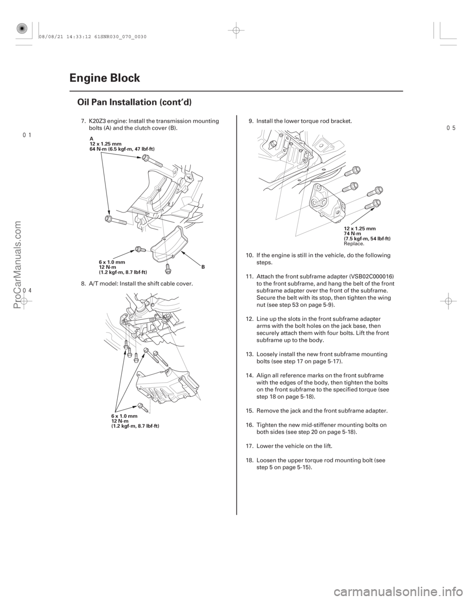
B
6x1.0mm
12 N·m
(1.2 kgf·m, 8.7 lbf·ft)
A
12x1.25mm
64N·m(6.5kgf·m,47lbf·ft)
6x1.0mm
12 N·m
(1.2 kgf·m, 8.7 lbf·ft) 12 x 1.25 mm
74 N·m
(7.5 kgf·m, 54 lbf·ft)
7. K20Z3 engine: Install the transmission mounting
bolts (A) and the clutch cover (B).
8. A/T model: Install the shift cable cover. 9. Install the lower torque rod bracket.
10. If the engine is still in the vehicle, do the following steps.
11. Attach the front subframe adapter (VSB02C000016) to the front subframe, and hang the belt of the front
subframe adapter over the front of the subframe.
Secure the belt with its stop, then tighten the wing
nut (see step 53 on page 5-9).
12. Line up the slots in the front subframe adapter arms with the bolt holes on the jack base, then
securely attach them with four bolts. Lift the front
subframe up to the body.
13. Loosely install the new front subframe mounting bolts (see step 17 on page 5-17).
14. Align all reference marks on the front subframe with the edges of the body, then tighten the bolts
on the front subframe to the specified torque (see
step 18 on page 5-18).
15. Remove the jack and the front subframe adapter.
16. Tighten the new mid-stiffener mounting bolts on both sides (see step 20 on page 5-18).
17. Lower the vehicle on the lift.
18. Loosen the upper torque rod mounting bolt (see step 5 on page 5-15).
Replace.
08/08/21 14:33:12 61SNR030_070_0030
ProCarManuals.com
DYNOMITE -2009-


