Page 1948 of 2893
���� ���
�(�#������������
�������������������
� �����)����
�µ
21-6821-68 Climate Control
Outside Air Temperature Sensor
Test
Outside Air Temperatur")
���
�(�#�'�����������
�������������������
�������)���� ���
�(�#�'�����������
�������������������
� �����)����
�µ
21-6821-68 Climate Control
Outside Air Temperature Sensor
Test
Outside Air Temperature Sensor
Replacement
OUTSIDE AIR TEMPERATURE SENSOR
10
14 0
32 10
5020
68 30
86
40 °C
104 °F
TEMPERATURE
RESISTANCE
(k )
12
11
10
98
7
6
5
4 3
2 1 A
B C
1. Remove the outside air temperature sensor
(see page 21-68).
2. Dip the sensor in ice water, and measure the resistance. Then pour warm water on the sensor,
and check for a change in resistance.
3. Compare the resistance reading between terminals No. 1 and No. 2 of the outside air temperature
sensor with the specifications shown in the graph;
the resistance should be within the specifications.
4. If the resistance is not as specified, replace the outside air temperature sensor (see page 21-68). 1. Remove the front grille cover (see page 20-163).
2. Lift the tab (A) to release the lock, then remove the
outside air temperature sensor (B) from the bracket.
Disconnect the 2P connector (C) from the outside
air temperature sensor.
3. Install the sensor in the reverse order of removal.
08/08/21 14:43:35 61SNR030_210_0069
ProCarManuals.com
DYNOMITE -2009-
Page 1950 of 2893
���
���
�(�#�'�����������
���
���������������
�������)����
21-70 Climate Control
Evaporator Temperature Sensor Test
EVAPORATOR TEMPERATURE SENSOR
40
30
20
10
RESISTANCE
(k )
10
5020
6830 °C
86 °F
TEMPERATURE
0
32
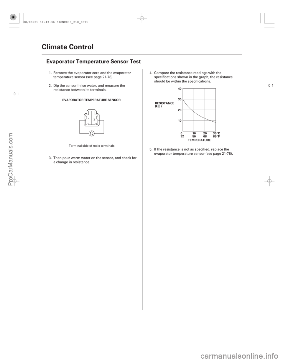
1. Remove the evaporator core and the evaporator
temperature sensor (see page 21-78).
2. Dip the sensor in ice water, and measure the resistance between its terminals.
3. Then pour warm water on the sensor, and check for a change in resistance. 4. Compare the resistance readings with the
specifications shown in the graph; the resistance
should be within the specifications.
5. If the resistance is not as specified, replace the evaporator temperature sensor (see page 21-78).
Terminal side of male terminals
08/08/21 14:43:36 61SNR030_210_0071
ProCarManuals.com
DYNOMITE -2009-
Page 1952 of 2893
���
���
�(�#����������������
�������
�������
� �����)����
Max Cool: About 0.5 V
Max Hot: About 4.5 V
21-7221-72 Climate Control
Air Mix Control Mot")
���
�(�#�'���������������
�������
�������
�������)���
���
�(�#�'���������������
�������
�������
� �����)����
Max Cool: About 0.5 V
Max Hot: About 4.5 V
21-7221-72 Climate Control
Air Mix Control Motor Test
Air Mix Control Motor Replacement
AIR MIX CONTROL MOTOR
B
A
NOTE: Before testing, check for HVAC DTCs (see page
21-9). 1. Disconnect the 7P connector from the air mix control motor.
Incorrectly applying power and ground to
the air mix control motor will damage it.
Follow the instructions carefully.
2. Connect battery power to terminal No. 1 of the air mix control motor, and ground terminal No. 2; the
air mix control motor should run, and stop at Max
Hot. If it doesn’t, reverse the connections; the air
mix control motor should run, and stop at Max Cool.
When the air mix control motor stops running,
disconnect battery power immediately.
3. If the air mix control motor did not run in step 2, remove it, then check the air mix control linkage
and door for smooth movement.
If the linkage and door move smoothly, replace the air mix control motor (see page 21-72).
If the linkage or door sticks or binds, repair them as needed.
If the air mix control motor runs smoothly, go to step 4.
4. Measure the resistance between terminals No. 5 and No. 7. It should be between 4.2 to 7.8 k .
5. Reconnect the air mix control motor 7P connector, then turn the ignition switch to ON (II).
6. Using the backprobe set, measure the voltage between terminals No. 3 and No. 7.
7. If either the resistance or voltage readings are not as specified, replace the air mix control motor
(see page 21-72). 1. Remove the driver’s dashboard undercover
(see page 20-103).
2. Disconnect the 7P connector (A) from the air mix control motor (B). Remove the self-tapping screws
and the air mix control motor from the heater unit.
3. Install the motor in the reverse order of removal. Make sure the pin on the motor is properly
engaged with the linkage. After installation, make
sure the motor runs smoothly.
08/08/21 14:43:37 61SNR030_210_0073
ProCarManuals.com
DYNOMITE -2009-
Page 1954 of 2893
���� ���
�(�#����������������
���������������
� �����)����
Recirculate: About 4.0 V
Fresh: About 1.0 V
21-7421-74 Climate Control
Recirculation Cont")
���
�(�#�'���������������
���������������
�������)���� ���
�(�#�'���������������
���������������
� �����)����
Recirculate: About 4.0 V
Fresh: About 1.0 V
21-7421-74 Climate Control
Recirculation Control Motor Test Recirculation Control Motor
Replacement
RECIRCULATION CONTROL MOTOR
A
B
NOTE: Before testing, check for HVAC DTCs (see page
21-9). 1. Disconnect the 7P connector from the recirculation control motor.
Incorrectly applying power and ground to
the recirculation control motor will damage it.
Follow the instructions carefully.
2. Connect battery power to terminal No. 1 of the recirculation control motor, and ground terminal
No. 2; the recirculation control motor should run,
and stop at Recirculate. If it doesn’t, reverse the
connections; the recirculation control motor should
run, and stop at Fresh. When the recirculation
control motor stops running, disconnect battery
power immediately.
3. If the recirculation control motor did not run in step 2, remove it, then check the recirculation control
linkage and door for smooth movement.
If the linkage and door move smoothly, replace the recirculation control motor (see page 21-74).
If the linkage or door sticks or binds, repair them as needed.
If the recirculation control motor runs smoothly, go to step 4.
4. Measure the resistance between terminals No. 5 and No. 7. It should be between 4.2 to 7.8 k .
5. Reconnect the recirculation control motor 7P connector, then turn the ignition switch to ON (II).
6. Using the backprobe set, measure the voltage between terminals No. 3 and No. 7.
7. If either the resistance or voltage readings are not as specified, replace the recirculation control motor
(see page 21-74). 1. Remove the glove box (see page 20-104) and the
kick panel (see page 20-66).
2. Disconnect the 7P connector (A) from the recirculation control motor (B). Remove the self-
tapping screws and the recirculation control motor
from the blower unit.
3. Install the motor in the reverse order of removal. Make sure the pin on the motor is properly
engaged with the linkage. After installation, make
sure the motor runs smoothly.
08/08/21 14:43:38 61SNR030_210_0075
ProCarManuals.com
DYNOMITE -2009-
Page 1955 of 2893
���� ���
����
�(�#����������������
���������������
� �����)����
21-7521-75
Climate Control Unit Removal/
Installation Dust and Pollen Filter Replace")
���
�(�#�'�����������
�����������
�����
�
� �����)���� ���
����
�(�#�'���������������
���������������
� �����)����
21-7521-75
Climate Control Unit Removal/
Installation Dust and Pollen Filter Replacement
B
A A
A
B
1. Remove the center panel: ’06-08 models with navigation (see page 23-155)
’06-08 models without navigation (see page23-80)
’09 model with navigation (see page 23-355)
’09 model without navigation (see page 23- 256)
2. Remove the dials (A), the self-tapping screws, and the climate control unit (B).
3. Install the control unit in the reverse order of removal. After installation, operate the various
functions to see whether works properly.
4. Run the self-diagnostic function to confirm that there are no problems in the system (see page
21-11). 1. Open the glove box. Remove the glove box stop on
each side, then let the glove box hang down
(see page 20-104).
2. Remove the dust and pollen filter assembly (A) from the evaporator.
3. Remove the filter (A) from the housing (B), and replace the filter.
4. Install the filter in the reverse order of removal. Make sure that there is no air leaking out of the
evaporator.
08/08/21 14:43:39 61SNR030_210_0076
ProCarManuals.com
DYNOMITE -2009-
Page 1956 of 2893
���
��������
����
�(�#�'���������������
�
��������������� �����)����
21-76 Climate Control
Blower Unit Removal/Installation
A
A A
B
B A
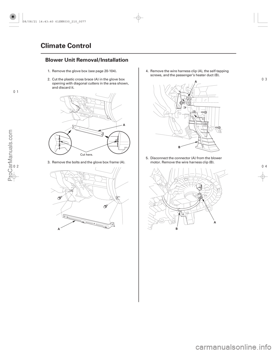
1. Remove the glove box (see page 20-104).
2. Cut the plastic cross brace (A) in the glove box
opening with diagonal cutters in the area shown,
and discard it.
3. Remove the bolts and the glove box frame (A). 4. Remove the wire harness clip (A), the self-tapping
screws, and the passenger’s heater duct (B).
5. Disconnect the connector (A) from the blower motor. Remove the wire harness clip (B).
Cut here.
08/08/21 14:43:40 61SNR030_210_0077
ProCarManuals.com
DYNOMITE -2009-
Page 1959 of 2893
���
��������
����
�(�#�'�����������
���
�������������
�
� �����)����
21-78 Climate Control
Evaporator Core Replacement
A
6x1.0mm
9.8 N·m (1.0 kgf·m, 7.2 lbf·ft)
6x1.0mm
9.8 N·m (1.0 kgf·m, 7.2 lbf·ft)
A B
C
D
6x1.0mm
9.8 N·m
(1.0 kgf·m, 7.2 lbf·ft) A
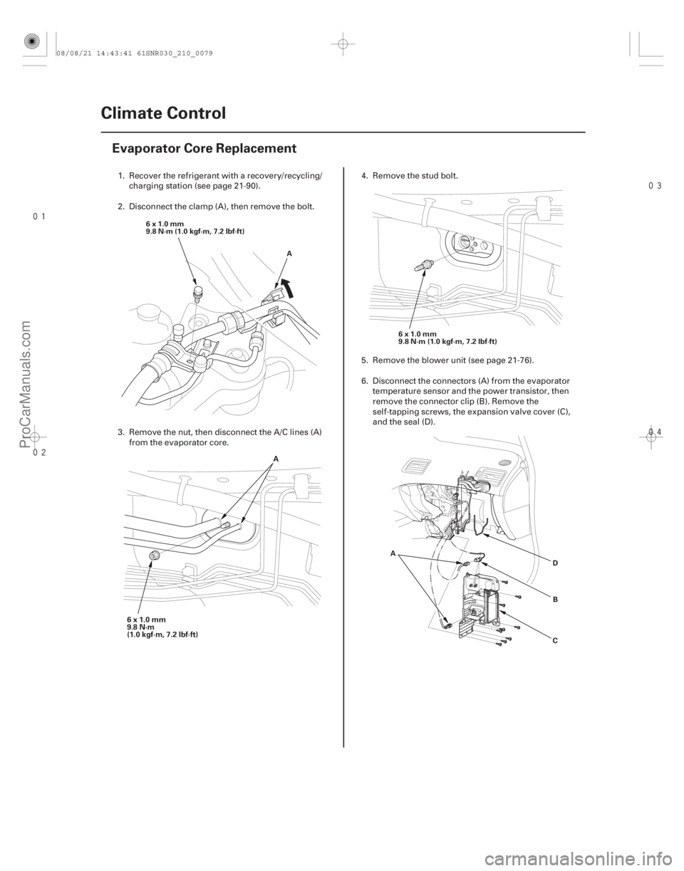
1. Recover the refrigerant with a recovery/recycling/
charging station (see page 21-90).
2. Disconnect the clamp (A), then remove the bolt.
3. Remove the nut, then disconnect the A/C lines (A) from the evaporator core. 4. Remove the stud bolt.
5. Remove the blower unit (see page 21-76).
6. Disconnect the connectors (A) from the evaporator
temperature sensor and the power transistor, then
remove the connector clip (B). Remove the
self-tapping screws, the expansion valve cover (C),
and the seal (D).
08/08/21 14:43:41 61SNR030_210_0079
ProCarManuals.com
DYNOMITE -2009-
Page 1961 of 2893
����
21-80Climate Control
Expansion Valve Replacement
A
5x0.8mm
3.2 N·m
(0.33 kgf·m,
2.4 lbf·ft)
B
1. Remove the evaporator core (see page 21-78).")
���
�(�#�'�����������
���
���������������
� �����)����
21-80Climate Control
Expansion Valve Replacement
A
5x0.8mm
3.2 N·m
(0.33 kgf·m,
2.4 lbf·ft)
B
1. Remove the evaporator core (see page 21-78).
2. Remove the bolts (A) and expansion valve (B).
3. Install the expansion valve in the reverse order of
removal and note these items:
If you’re installing a new expansion valve, add refrigerant oil (SP-10) (see page 21-7).
Replace the O-rings with new ones at each fitting, and apply a thin coat of refrigerant oil before
installing them. Be sure to use the correct O-rings
for HFC-134a (R-134a) to avoid leakage.
Immediately after using the oil, reinstall the cap on the container, and seal it to avoid moisture
absorption.
Do not spill the refrigerant oil on the vehicle; it may damage the paint; if the refrigerant oil
contacts the paint, wash it off immediately.
Make sure that there is no air leakage.
Charge the system (see page 21-92).
08/08/21 14:43:42 61SNR030_210_0081
ProCarManuals.com
DYNOMITE -2009-