Page 1355 of 2893
���
17-32EPS Components
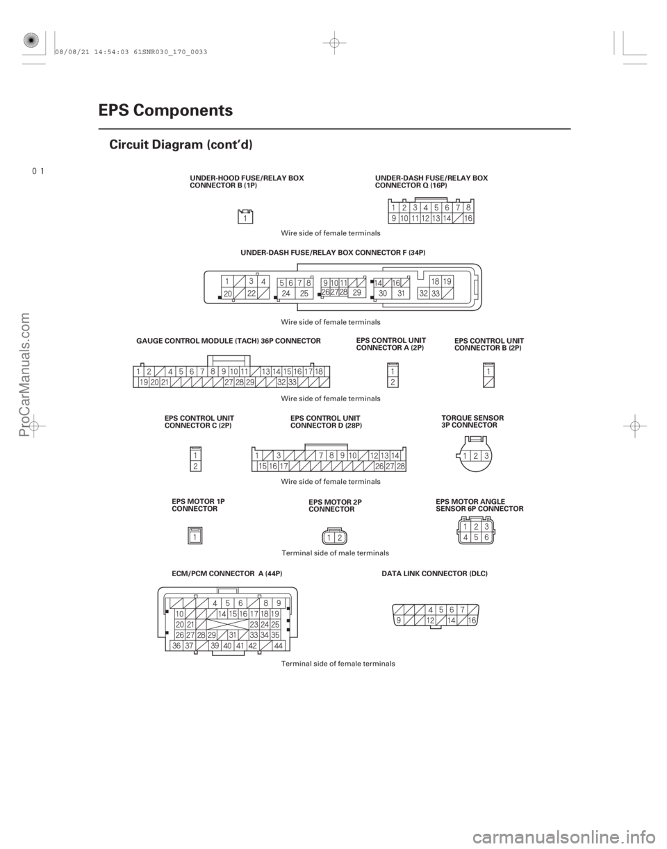
Circuit Diagram (cont’d)
EPS CONTROL UNIT
CONNECTOR A (2P)
EPS CONTROL UNIT
CONNECTOR B (2P)
DATA LINK CONNECTOR (DLC)
GAUGE CONTROL MODULE (TACH) 36P CONNECTOR
UNDER-DASH FUSE/RELAY BOX CONNECTOR F (34P)
EPS CONTROL UNIT
CONNECTOR D (28P)
EPS CONTROL UNIT
CONNECTOR C (2P) TORQUE SENSOR
3P CONNECTOR
UNDER-DASH FUSE/RELAY BOX
CONNECTOR Q (16P)
UNDER-HOOD FUSE/RELAY BOX
CONNECTOR B (1P)
ECM/PCM CONNECTOR A (44P) EPS MOTOR 1P
CONNECTOR EPS MOTOR 2P
CONNECTOREPS MOTOR ANGLE
SENSOR 6P CONNECTOR
Wire side of female terminals
Wire side of female terminals
Terminal side of male terminals
Terminal side of female terminals
Wire side of female terminals
Wire side of female terminals
08/08/21 14:54:03 61SNR030_170_0033
ProCarManuals.com
DYNOMITE -2009-
Page 1459 of 2893
�
��
Suspension
............................
............................
Front and Rear Suspension . 18-2
............................................
..")
�(�#�'�������������������������
�����
�/�����)�
��
Suspension
............................
............................
Front and Rear Suspension . 18-2
............................................
............................................
Front Suspension . 18-14
..............................................
..............................................
Rear Suspension . 18-31
TPMS (Tire Pressure Monitoring System) (’08-09 Models)
........................................
........................................
...................................
....................................... ..............................
.....................................................
............................................................ ....................................................................................................................................................
........................................
........................................
...................................
....................................... ..............................
.....................................................
............................................................ ....................................................................................................................................................
Component Location Index . 18-48
General Troubleshooting Information . 18-49
Memorizing the Tire Pressure Sensor ID . 18-52
Tire Pressure Sensor Location . 18-53
DTC Troubleshooting Index . 18-55
Symptom Troubleshooting Index . 18-56
System Description . 18-57
Circuit Diagram . 18-61
DTC Troubleshooting . 18-63
Symptom Troubleshooting . 18-71
TPMS Control Unit Replacement . 18-75
Tire Pressure Sensor Replacement . 18-76
08/08/21 14:58:20 61SNR030_180_0047
ProCarManuals.com
DYNOMITE -2009-
Page 1474 of 2893
���
�(�#�'���������������
�����
�����������������)����
�´
18-61
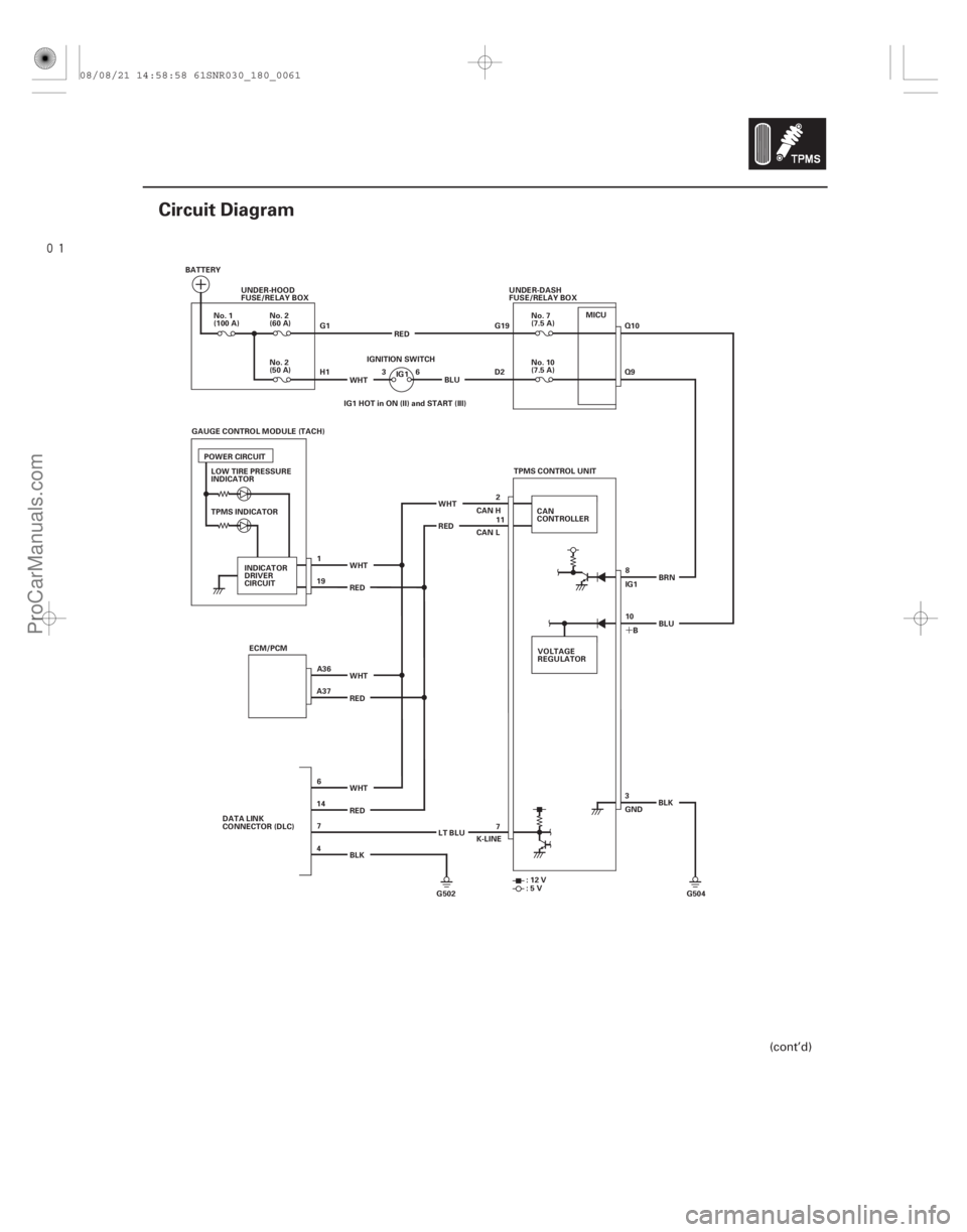
Circuit Diagram
BATTERYUNDER-HOOD
FUSE/RELAY BOX
G1
H1WHT 36
IGNITION SWITCH
No. 10
(7.5 A)
No. 2
(60 A)
No. 2
(50 A)
No. 1
(100 A)
No. 7
(7.5 A)
UNDER-DASH
FUSE/RELAY BOX
G19
D2
TPMS INDICATOR ECM/PCM WHT
RED
WHT
RED
BLK TPMS CONTROL UNIT
CAN
CONTROLLER
RED WHT RED WHT
VOLTAGE
REGULATOR8
10 IG1
B BRN
3
GND BLK
G502 G504 K-LINE
:12V
:5V
CAN H
CAN L
IG1
POWER CIRCUIT
INDICATOR
DRIVER
CIRCUIT IG1 HOT in ON (II) and START (III)
DATA LINK
CONNECTOR (DLC) LT BLUBLU
RED
BLU
2
11
LOW TIRE PRESSURE
INDICATOR
GAUGE CONTROL MODULE (TACH)
1
A36
A37 19
6
14 7
4 7Q10
Q9
MICU
(cont’d)
08/08/21 14:58:58 61SNR030_180_0061
ProCarManuals.com
DYNOMITE -2009-
Page 1475 of 2893
����
18-62TPMS
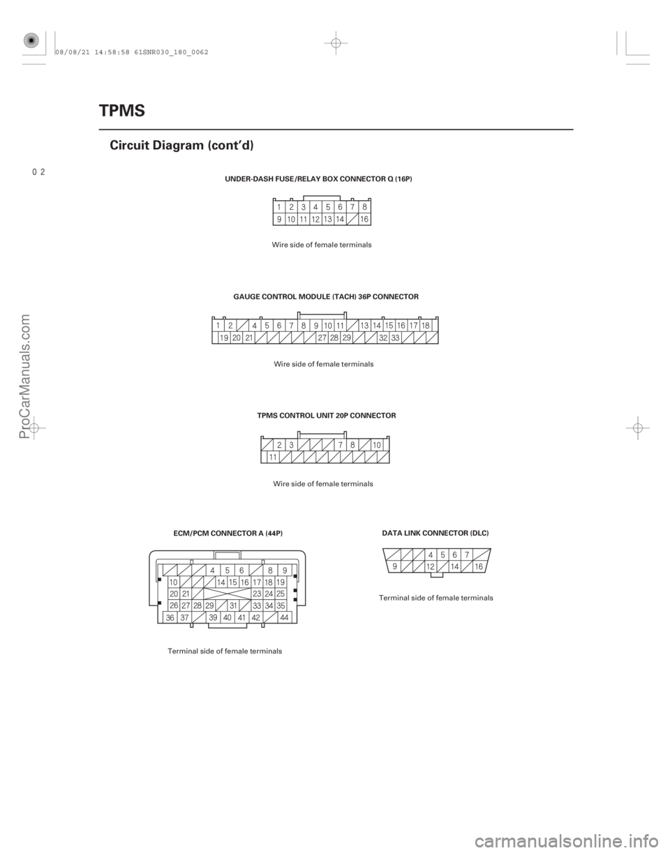
Circuit Diagram (cont’d)
DATA LINK CONNECTOR (DLC)
TPMS CONTROL UNIT 20P CONNECTOR
UNDER-DASH FUSE/RELAY BOX CONNECTOR Q (16P)
ECM/PCM CONNECTOR A (44P) GAUGE CONTROL MODULE (TACH) 36P CONNECTOR
Wire side of female terminals
Terminal side of female terminals Wire side of female terminals
Wire side of female terminals
Terminal side of female terminals
08/08/21 14:58:58 61SNR030_180_0062
ProCarManuals.com
DYNOMITE -2009-
Page 1492 of 2893
����
Brakes
Conventional Brake Components......................
......................
ABS (Anti-lock Brake System)
Components (’06-07 Models) . 19-47
.")
�(�#�'�������������������������
�����
�/�����)����
Brakes
Conventional Brake Components......................
......................
ABS (Anti-lock Brake System)
Components (’06-07 Models) . 19-47
......................
......................
VSA (Vehicle Stability Assist) System
Components (’07-09 Models) . 19-95
................................................................
.....................................................................
........................................
............................................................... ................
............................................... ...................
.......................................... ..................................... ..........
........................................ ...................................
..................................... ....................................
.........................................
...................................................... ....................................... ...........
......................................... ....................................
......................................
........................................... .................................
............................................ .............................
............................................................ ................................
Special Tools . 19-2
Component Location Index . 19-3
Brake System Inspection and Test . 19-4
Symptom Troubleshooting . 19-5
Brake Pedal and Brake Pedal Position Switch
Adjustment . 19-6
Parking Brake Inspection and Adjustment . 19-7
Brake System Bleeding . 19-9
Brake System Indicator Circuit Diagram . 19-10
Parking Brake Switch Test . 19-11
Brake Fluid Level Switch Test . 19-11
Front Brake Pad Inspection and Replacement . 19-12
Front Brake Disc Inspection . 19-19
Front Brake Disc Replacement . 19-21
Front Brake Caliper Overhaul . 19-22
Master Cylinder Replacement . 19-24
Master Cylinder Inspection . 19-25
Brake Booster Test . 19-26
Brake Booster Replacement . 19-27
Rear Brake Pad Inspection and Replacement . 19-29
Rear Brake Disc Inspection . 19-32
Rear Brake Disc Replacement . 19-34
Rear Brake Caliper Overhaul . 19-35
Brake Pedal Replacement . 19-36
Brake Hose and Line Inspection . 19-37
Brake Hose Replacement . 19-38
Parking Brake Cable Replacement . 19-40
Parking Brake Lever Grip and Cover Replacement . 19-41
Brake Pedal Cover Replacement . 19-45
08/08/21 15:00:43 61SNR030_190_0001
ProCarManuals.com
DYNOMITE -2009-
Page 1494 of 2893
����
19-3
Component Location Index
BRAKE SYSTEM INDICATOR BRAKE HOSE and LINE
REAR BRAKE
FRONT BRAKE PARKING BRAKE
BRAKE BOOSTER
MASTER CYLINDER
BR")
����
�(�#�'�����������
���������������������������)����
19-3
Component Location Index
BRAKE SYSTEM INDICATOR BRAKE HOSE and LINE
REAR BRAKE
FRONT BRAKE PARKING BRAKE
BRAKE BOOSTER
MASTER CYLINDER
BRAKE PEDAL
Circuit Diagram, page 19-10
Parking Brake Switch Test, page 19-11
Brake Fluid Level Switch Test, page 19-11
Inspection, page 19-37
Brake Hose Replacement, page 19-38
Pad Inspection andReplacement, page 19-29
Disc Inspection, page 19-32
Disc Replacement, page 19-34
Caliper Overhaul, page 19-35
Pad Inspection and Replacement,
page 19-12
Disc Inspection, page 19-19
Disc Replacement, page 19-21
Caliper Overhaul, page 19-22 Inspection and Adjustment, page 19-7
Cable Replacement, page 19-40
Lever Grip and Cover Replacement,
page 19-41
Test, page 19-26
Replacement, page 19-27
Brake System Bleeding,
page 19-9
Replacement, page 19-24
Inspection, page 19-25
Brake Pedal and Brake PedalPosition Switch Adjustment,
page 19-6
Replacement, page 19-36
Cover Replacement, page 19-45
08/08/21 15:00:49 61SNR030_190_0003
ProCarManuals.com
DYNOMITE -2009-
Page 1502 of 2893
���
�(�#�'�����������
�����������
���������������)����
19-10Conventional Brake Components
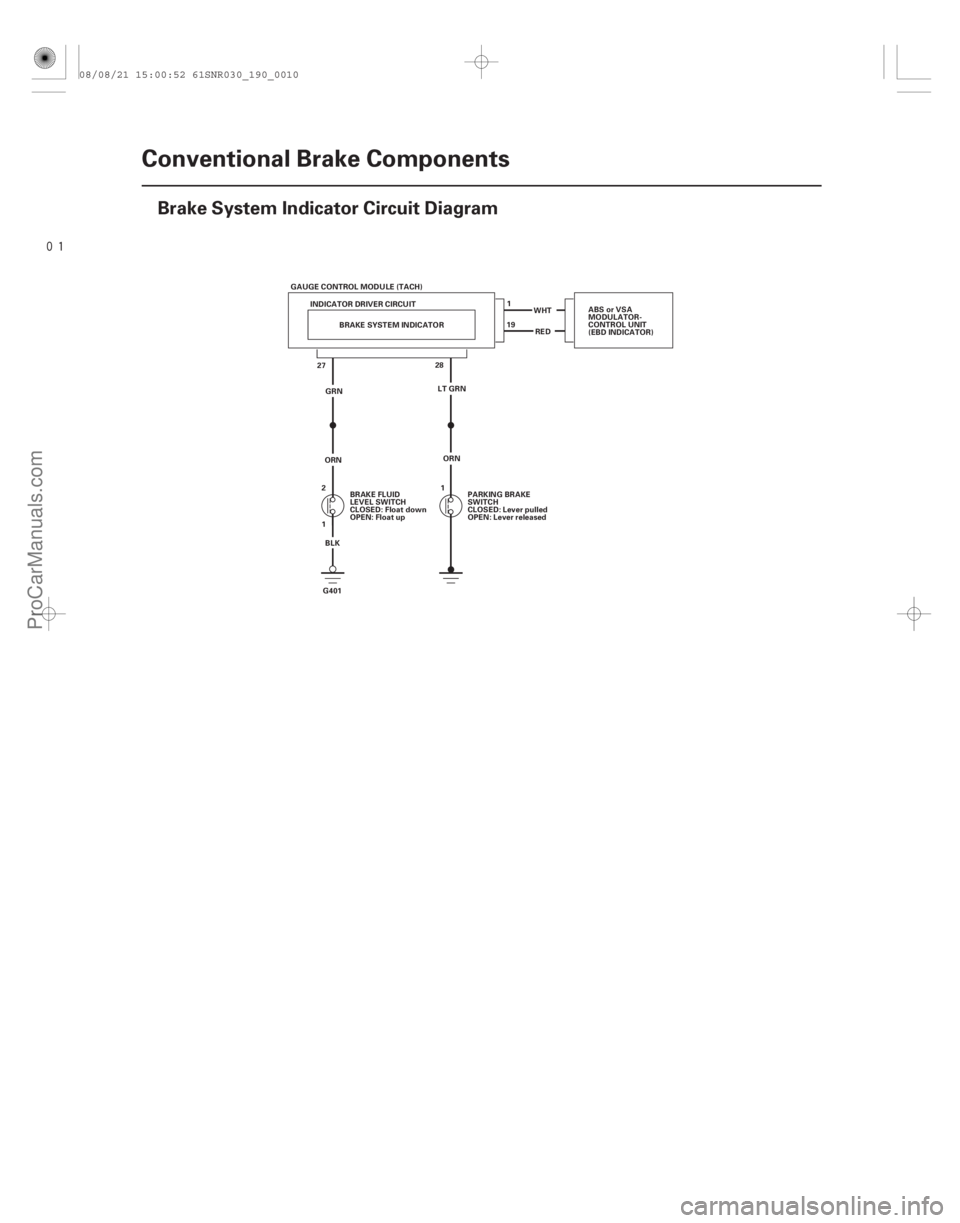
Brake System Indicator Circuit Diagram
BRAKE FLUID
LEVEL SWITCH
CLOSED: Float down
OPEN: Float up
PARKING BRAKE
SWITCH
CLOSED: Lever pulled
OPEN: Lever released
BRAKE SYSTEM INDICATOR
GAUGE CONTROL MODULE (TACH)
INDICATOR DRIVER CIRCUIT
27 RED
WHT
1
19
28
G401 BLKGRN
ORN LT GRN ABS or VSA
MODULATOR-
CONTROL UNIT
(EBD INDICATOR)
ORN
2
1 1
08/08/21 15:00:52 61SNR030_190_0010
ProCarManuals.com
DYNOMITE -2009-
Page 1540 of 2893
����
Brakes
....................................
Conventional Brake Components . 19-1
ABS (Anti-lock Brake System)
Components (’06-07 Models)
..........")
�(�#�'�������������������������
�������/�����)����
Brakes
....................................
Conventional Brake Components . 19-1
ABS (Anti-lock Brake System)
Components (’06-07 Models)
...................... ......................
VSA (Vehicle Stability Assist) System
Components (’07-09 Models) . 19-95
........................................
......................
....................................... ..............................
.....................................................
............................................................ ..........................................................................................
........................................ ...........................
Component Location Index
. 19-48
General Troubleshooting Information . 19-49
DTC Troubleshooting Index . 19-52
Symptom Troubleshooting Index . 19-55
System Description . 19-56
Circuit Diagram . 19-62
DTC Troubleshooting . 19-65
Symptom Troubleshooting . 19-88
ABS Modulator-Control Unit Removal and Installation . 19-90
Wheel Speed Sensor Replacement . 19-92
08/08/21 15:02:12 61SNR030_190_0047
ProCarManuals.com
DYNOMITE -2009-