Page 1967 of 2893
����
�µ�µ
�µ
Clearance: 0.35 0.65 mm (0.014 0.026 in.)Field Coil Resistance: 3.15 3.45 20 °C (68 °F)
21-85
A/C Compressor Clutch C")
���
��������
����
�(�#�'�����������
���
�
���
�
�����
�
�"�����)����
�µ�µ
�µ
Clearance: 0.35 0.65 mm (0.014 0.026 in.)Field Coil Resistance: 3.15 3.45 20 °C (68 °F)
21-85
A/C Compressor Clutch Check
A
B
A
1. Check the armature plate for discoloration, peeling,or other damage. If there is damage, replace the
clutch set (see page 21-86).
2. Check the rotor pulley bearing play and drag by rotating the rotor pulley by hand. Replace the
clutch set with a new one if it is noisy or has
excessive play/drag (see page 21-86).
3. Measure the clearance between the rotor pulley (A) and the armature plate (B) all the way around. If the
clearance is not within specified limits, remove the
armature plate (see page 21-86) and add or remove
shims as needed to increase or decrease clearance.
NOTE: The shims are available in four thicknesses:
0.1 mm, 0.2 mm, 0.4 mm, and 0.5 mm. 4. Check the thermal protector for continuity between
the A/C compressor clutch connector terminals
No. 1 and No. 3. If there is no continuity, replace the
thermal protector (see page 21-87).
NOTE: The thermal protector will have no
continuity above about 122 to 128 °C (252 to 262 °F).
When the temperature drops below about 116 to
104 °C (241 to 219 °F), the thermal protector will
have continuity.
5. Disconnect the field coil connector (A). Check resistance of the field coil. If resistance is not within
specifications, replace the field coil (see page
21-86).
08/08/21 14:43:46 61SNR030_210_0086
ProCarManuals.com
DYNOMITE -2009-
Page 2188 of 2893
����
������(�#�'���������������
�����������������������)����
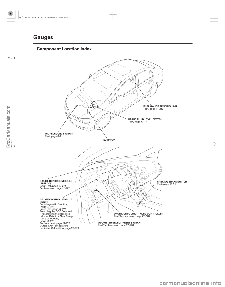
22-238Gauges
Component Location Index
OIL PRESSURE SWITCH
ECM/PCMBRAKE FLUID LEVEL SWITCH
FUEL GAUGE SENDING UNIT
GAUGE CONTROL MODULE
(TACH) ODOMETER SELECT/RESET SWITCHDASH LIGHTS BRIGHTNESS CONTROLLER
GAUGE CONTROL MODULE
(SPEEDO)
PARKING BRAKE SWITCH
Test, page 8-9
Test, page 19-11
Test, page 11-340
Self-diagnostic Function, page 22-241
Input Test, page 22-271
Rewriting the ODO Data and Transferring Maintenance
Minder Data to a New Gauge
Control Module,
page 22-276
Replacement, page 22-277
Outside Air Temperature Indicator Calibration, page 22-279 Test/Replacement, page 22-278Test/Replacement, page 22-278
Input Test, page 22-274
Replacement, page 22-277
Test, page 19-11
08/08/21 14:28:53 61SNR030_220_0240
ProCarManuals.com
DYNOMITE -2009-
Page 2195 of 2893
�����
�µ
�µ
22-245
C
(LED)
LCD DISPLAY
LCD DRIVERMAIN CIRCUIT
33
ORN
ORN 32
LT GRN
3 1
PUR (LED)
(LED)
(LED)
C
LCD DISPLAY
B
A
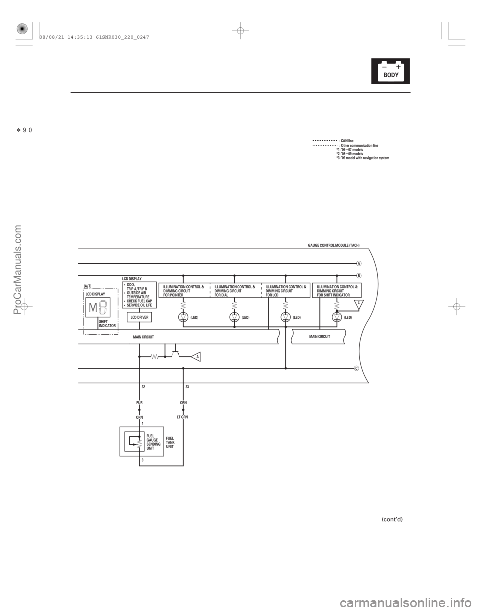
GAUGE CONTROL MODULE (TACH)
ODO,
TRIP A/TRIP B
OUTSIDE AIR
TEMPERATURE
CHECK FUEL CAP
SERVICE OIL LIFE ILLUMINATION CONTROL &
DIMMING CIRCUIT
FOR POINTER
ILLUMINATION CONTROL &
DIMMING CIRCUIT
FOR DIALILLUMINATION CONTROL &
DIMMING CIRCUIT
FOR LCD
FUEL
GAUGE
SENDING
UNIT FUEL
TANK
UNIT ILLUMINATION CONTROL &
DIMMING CIRCUIT
FOR SHIFT INDICATOR
SHIFT
INDICATOR
(A/T)
MAIN CIRCUIT
A :CANline
: Other communication line
*1: ’06 07 models
*2: ’08 09 models
*3: ’09 model with navigation system
(cont’d)
08/08/21 14:35:13 61SNR030_220_0247
ProCarManuals.com
DYNOMITE -2009-
Page 2201 of 2893
�����
�µ
22-251
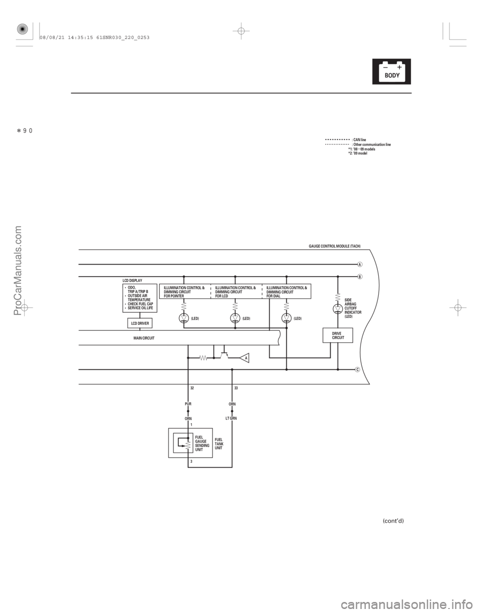
:CANline
MAIN CIRCUIT 33
ORN
ORN 32
LT GRN
3 1
PUR (LED)
(LED)
(LED)
C
LCD DISPLAY
B
A
GAUGE CONTROL MODULE (TACH)
ILLUMINATION CONTROL &
DIMMING CIRCUIT
FOR POINTER ILLUMINATION CONTROL &
DIMMING CIRCUIT
FOR LCDILLUMINATION CONTROL &
DIMMING CIRCUIT
FOR DIAL
FUEL
GAUGE
SENDING
UNIT FUEL
TANK
UNIT : Other communication line
DRIVE
CIRCUIT
A
ODO,
TRIP A/TRIP B
OUTSIDE AIR
TEMPERATURE
CHECK FUEL CAP
SERVICE OIL LIFE
LCD DRIVER SIDE
AIRBAG
CUTOFF
INDICATOR
(LED)*1: ’08 09 models
*2: ’09 model
(cont’d)
08/08/21 14:35:15 61SNR030_220_0253
ProCarManuals.com
DYNOMITE -2009-