Page 507 of 2893

���
�(�#�'��������� �����
�������*���
�����������)����
�µ
�µ
�µ
�µ
�µ
�µ �µ
�µ
DTC U0122:
YES
NO
YES
NO
YES
NO YES
NO
11-184PGM-FI System
DTC Troubleshooting (cont’d)
CANH (WHT)
CANH (WHT) ECM/PCM CONNECTOR A (44P)
VSA MODULATOR-CONTROL
UNIT 37P CONNECTOR
F-CAN Malfunction (ECM/PCM-
VSA Modulator-Control Unit)
NOTE: Before you troubleshoot, record all freeze data
and any on-board snapshot, and review the general
troubleshooting information (see page 11-3).
1. Turn the ignition switch to ON (II).
2. Check for Temporary DTCs or DTCs with the HDS.
Go to the troubleshooting for DTC U 0028.
Go to step 3.
3. Clear the DTC with the HDS.
4. Check for Temporary DTCs or DTCs with the HDS.
Go to step 5.
Intermittent failure, the system is OK at this
time. Check for poor connections or loose terminals
at the VSA modulator-control unit and the ECM/
PCM.
5. Check for communication to the VSA system with the HDS.
Go to step 6.
Go to the DLC circuit troubleshooting
(see page 11-204).
6. Turn the ignition switch to LOCK (0).
7. Jump the SCS line with the HDS.
8. Disconnect the VSA modulator-control unit 37P connector (see page 19- 171).
9. Disconnect ECM/PCM connector A (44P). 10. Check for continuity between ECM/PCM connector
terminal A36 and VSA modulator-control unit 37P
connector terminal No. 15.
Go to step 11.
Repair open in the wire between the ECM/
PCM (A36) and the VSA modulator-control unit,
then go to step 12.
Terminal side of female terminals
Wire side of female terminals
Ar e DT C U 0028 and U 0122 i nd i cat ed at t he same time?
Is DTC U0122 indicated?
Does the HDS communicate with the V SAmod ul at or -cont r ol uni t ? Is there continuity?
08/08/21 14:21:46 61SNR030_110_0184
ProCarManuals.com
DYNOMITE -2009-
Page 508 of 2893

�����µ
�µ �µ
�µ
YES
NO YES
NO
11-185
CANL (RED)
CANL (RED)
VSA MODULATOR-CONTROL
UNIT 37P CONNECTOR
ECM/PCM CONNECTOR A (44P)
11. Check for continuity between ECM/PCM connector
terminal A37 and VSA modulator-control unit 37P
connector terminal No. 1.
Substitute a known-good VSA modulator-
control unit (see page 19-171), then go to step 12
and recheck. If DTC U0122 is not indicated, replace
the original VSA modulator-control unit (see page
19-171), then go to step 12.
Repair open in the wire between the ECM/
PCM (A37) and the VSA modulator-control unit,
then go to step 12. 12. Reconnect all connectors.
13. Turn the ignition switch to ON (II).
14. Reset the ECM/PCM with the HDS.
15. Do the ECM/PCM idle learn procedure (see page
11-310).
16. Check for Temporary DTCs or DTCs with the HDS.
Check for poor connections or loose
terminals at the VSA modulator-control unit and
theECM/PCM,thengotostep1.
Troubleshooting is complete. If any other
Temporary DTCs or DTCs are indicated, go to the
indicated DTC’s troubleshooting.
Wire side of female terminals Terminal side of female terminals
Is there continuity? Is DTC U0122 indicated?
08/08/21 14:21:47 61SNR030_110_0185
ProCarManuals.com
DYNOMITE -2009-
Page 509 of 2893

���
����
�(�#�'��������� �����
�������*���
���
�������)����
�µ
�µ
�µ
�µ
�µ
�µ �µ
�µ
DTC U0131:
YES
NO
YES
NO
YES
NO YES
NO
11-186PGM-FI System
DTC Troubleshooting (cont’d)
ECM/PCM CONNECTOR A (44P)
CANH (WHT)
JUMPER WIRE
EPS CONTROL UNIT CONNECTOR D (28P) CANH (WHT)
F-CAN Malfunction (ECM/PCM-
EPS Control Unit)
NOTE: Before you troubleshoot, record all freeze data
and any on-board snapshot, and review the general
troubleshooting information (see page 11-3).
1. Turn the ignition switch to ON (II).
2. Check for Temporary DTCs or DTCs with the HDS.
Go to the troubleshooting for DTC U 0028.
Go to step 3.
3. Clear the DTC with the HDS.
4. Check for Temporary DTCs or DTCs with the HDS.
Go to step 5.
Intermittent failure, the system is OK at this
time. Check for poor connections or loose terminals
at the EPS control unit and the ECM/PCM.
5. Check that the HDS communicates with the EPS system.
Go to step 6.
Go to the DLC circuit troubleshooting
(see page 11-204).
6. Turn the ignition switch to LOCK (0).
7. Jump the SCS line with the HDS.
8. Disconnect EPS control unit connector D (28P) (see page 17-84).
9. Disconnect ECM/PCM connector A (44P) 10. Connect ECM/PCM connector terminal A36 to body
ground with a jumper wire.
11. Check for continuity between EPS control unit connector D (28P) terminal No. 1 and body ground.
Go to step 12.
Repair open in the wire between the ECM/
PCM (A36) and the EPS control unit, then go to step
14.
Terminal side of female terminals
Wire side of female terminals
Ar e DT C U 0028 and U 0131 i nd i cat ed at t he sametime?
Is DT C U0131 ind icated ?
Does the HDS communicate with the EPS controluni t ? I s t her e cont i nui t y ?
08/08/21 14:21:47 61SNR030_110_0186
ProCarManuals.com
DYNOMITE -2009-
Page 510 of 2893

����
�����µ
�µ �µ
�µ
YES
NO YES
NO
11-187
ECM/PCM CONNECTOR A (44P)
CANL (RED)
JUMPER WIRE
EPS CONTROL UNIT CONNECTOR D (28P) CANL (RED)
12. Connect ECM/PCM connector terminal A37 to body ground with a jumper wire.
13. Check for continuity between EPS control unit connector D (28P) terminal No. 15 and body ground.
Substitute a known-good EPS control unit
(see page 17-84), then go to step 14 and recheck. If
no DTCs are indicated, replace the original EPS
control unit (see page 17-84), then go to step 14.
Repair open in the wire between the ECM/
PCM (A37) and the EPS control unit, then go to step
14. 14. Reconnect all connectors.
15. Turn the ignition switch to ON (II).
16. Reset the ECM/PCM with the HDS.
17. Do the ECM/PCM idle learn procedure (see page
11-310).
18. Check for Temporary DTCs or DTCs with the HDS.
Check for poor connections or loose
terminals at the EPS control unit and the ECM/PCM,
then go to step 1.
Troubleshooting is complete. If any other
Temporary DTCs or DTCs are indicated, go to the
indicated DTC’s troubleshooting.
Terminal side of female terminals
Wire side of female terminals
Is there continuity? Is DT C U0131 ind icated ?
08/08/21 14:21:48 61SNR030_110_0187
ProCarManuals.com
DYNOMITE -2009-
Page 511 of 2893

���
����
�(�#�'��������� �����
�������*���
�����������)����
�µ
�µ
�µ
�µ
�µ
�µ
DTC U0155:
YES
NO
YES
NO
YES
NO
11-188PGM-FI System
DTC Troubleshooting (cont’d)
GAUGE CONTROL MODULE (TACH) 36P CONNECTOR
CANH (WHT)
JUMPER WIRE
ECM/PCM CONNECTOR A (44P)CANH (WHT)
F-CAN Malfunction (ECM/PCM-
Gauge Control Module)
NOTE: Before you troubleshoot, record all freeze data
and any on-board snapshot, and review the general
troubleshooting information (see page 11-3).
1. Turn the ignition switch to ON (II).
2. Clear the DTC with the HDS.
3. Check for Temporary DTCs or DTCs with the HDS.
Go to step 4.
Intermittent failure, the system is OK at this
time. Check for poor connections or loose terminals
at the gauge control module (tach) and the ECM/
PCM.
4. Check for body electrical DTCs in the DTCs MENU with the HDS.
Go to step 5.
Do the gauge control module (tach) input test
(see page 22-271).
5. Turn the ignition switch to LOCK (0).
6. Jump the SCS line with the HDS.
7. Remove the gauge control module (tach) (see page 22-277).
8. Disconnect ECM/PCM connector A (44P). 9. Connect gauge control module (tach) 36P
connector terminal No. 1 to body ground with a
jumper wire.
10. Check for continuity between ECM/PCM connector terminal A36 and body ground.
Go to step 11.
Repair open in the wire between the ECM/
PCM (A36) and the gauge control module (tach),
then go to step 13.
Wire side of female terminals
Terminal side of female terminals
Is DTC U0155 indicated? I s DT C B1168, B1169, and / or B117 8 i nd i cat ed ? Is there continuity?
08/08/21 14:21:48 61SNR030_110_0188
ProCarManuals.com
DYNOMITE -2009-
Page 512 of 2893

����
�����µ
�µ �µ
�µ
YES
NO YES
NO
11-189
GAUGE CONTROL MODULE (TACH) 36P CONNECTOR
CANL (RED)
JUMPER WIRE
ECM/PCM CONNECTOR A (44P) CANL (RED)
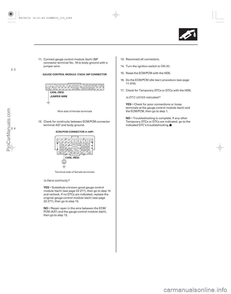
11. Connect gauge control module (tach) 36Pconnector terminal No. 19 to body ground with a
jumper wire.
12. Check for continuity between ECM/PCM connector terminal A37 and body ground.
Substitute a known-good gauge control
module (tach) (see page 22-277), then go to step 14
and recheck. If no DTCs are indicated, replace the
original gauge control module (tach) (see page
22-277), then go to step 13.
Repair open in the wire between the ECM/
PCM (A37) and the gauge control module (tach),
then go to step 13. 13. Reconnect all connectors.
14. Turn the ignition switch to ON (II).
15. Reset the ECM/PCM with the HDS.
16. Do the ECM/PCM idle learn procedure (see page
11-310).
17. Check for Temporary DTCs or DTCs with the HDS.
Check for poor connections or loose
terminals at the gauge control module (tach) and
theECM/PCM,thengotostep1.
Troubleshooting is complete. If any other
Temporary DTCs or DTCs are indicated, go to the
indicated DTC’s troubleshooting.
Wire side of female terminals
Terminal side of female terminals
Is there continuity? Is DTC U0155 indicated?
08/08/21 14:21:49 61SNR030_110_0189
ProCarManuals.com
DYNOMITE -2009-
Page 513 of 2893
�(�#�'�������
� �����
�������*���������������)�����µ
�µ
DTC U0300:
YES
NO
11-190 PGM-FI System
DTC Troubleshooting (cont’d)
PGM-FI System and A/T System
Program Version Mismatch
NOTE:
Before you troubleshoot, record all freeze data and any on-board snapshot, and review the general
troubleshooting information (see page 11-3).
Do not turn the ignition switch to LOCK (0) while updating the PCM. If you turn the ignition switch to
LOCK (0) before completion, the PCM will be
damaged.
1. Do the PCM update procedure (PGM-FI system and A/T system) (see page 11-227).
2. Check for Temporary DTCs or DTCs with the HDS.
Replace the original PCM (see page 11-228).
The update is complete. If any other
Temporary DTCs or DTCs are indicated, go to the
indicated DTC’s troubleshooting.
Is DT C U0300 ind icated ?
08/08/21 14:21:49 61SNR030_110_0190
ProCarManuals.com
DYNOMITE -2009-
Page 514 of 2893

�µ�µ
�µ
���
�(�#�'���������������������������������������)����
�µ
�µ
YES
NO
11-191
F-CAN Circuit Troubleshooting
ECM/PCM CONNECTOR A (44P)
CANL (RED)
CANH (WHT)
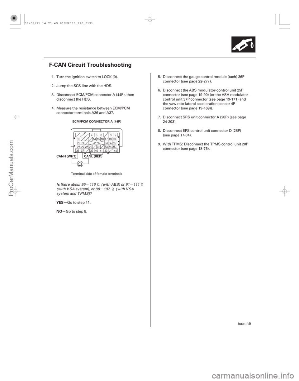
1. Turn the ignition switch to LOCK (0).
2. Jump the SCS line with the HDS.
3. Disconnect ECM/PCM connector A (44P), then
disconnect the HDS.
4. Measure the resistance between ECM/PCM connector terminals A36 and A37.
Go to step 41.
Go to step 5. 5. Disconnect the gauge control module (tach) 36P
connector (see page 22- 277).
6. Disconnect the ABS modulator-control unit 25P connector (see page 19-90) (or the VSA modulator-
control unit 37P connector (see page 19-171) and
the yaw rate-lateral acceleration sensor 4P
connector (see page 19-169)).
7. Disconnect SRS unit connector A (28P) (see page 24-203).
8. Disconnect EPS control unit connector D (28P) (see page 17-84).
9. With TPMS: Disconnect the TPMS control unit 20P connector (see page 18-75).
(cont’d)
Terminal side of female terminals
I s t her e about 95 116 ( w i t h ABS) or 91 111( w i t h V SA sy st em), or 88 107 ( w i t h V SAsy st em and T PM S)?
08/08/21 14:21:49 61SNR030_110_0191
ProCarManuals.com
DYNOMITE -2009-