Page 358 of 2893

Accelerator Pedal Position (APP) Sensor
Electronic Throttle Control System
11-35
TERMINAL
MAGNET O-RING O-RING
ZIRCONIA
ELEMENT SENSOR")
����
��������
M/T
Secondary Heated Oxygen Sensor (Secondary HO2S)
Accelerator Pedal Position (APP) Sensor
Electronic Throttle Control System
11-35
TERMINAL
MAGNET O-RING O-RING
ZIRCONIA
ELEMENT SENSOR
TERMINALS
HEATER
TERMINALS
HEATER
APP SENSOR A/B
ACCELERATOR
PEDAL MODULE
The secondary HO2S detects the oxygen content in the
exhaust gas downstream of the three way catalytic
converter (TWC), and sends signals to the ECM/PCM
which varies the duration of fuel injection accordingly.
To stabilize its output, the sensor has an internal heater.
The ECM/PCM compares the HO2S output with the A/F
sensor output to determine catalyst efficiency. The
secondary HO2S is on the TWC. The throttle is electronically controlled by the electronic
throttle control system. Refer to the system diagram to
see a functional layout of the system.
Idle control: When the engine is idling, the ECM/PCM
controls the throttle actuator to maintain the proper idle
speed according to engine loads.
Acceleration control: When the accelerator pedal is
pressed, the ECM/PCM opens the throttle valve,
depending on the accelerator pedal position (APP)
sensor signal.
Cruise control: The ECM/PCM controls the throttle
actuator to maintain the set speed when the cruise
control is operating. The throttle actuator takes the
place of the cruise control actuator.
As the accelerator pedal position changes, the sensor
varies the signal voltage to the ECM/PCM.
(cont’d)
08/08/21 14:13:39 61SNR030_110_0035
ProCarManuals.com
DYNOMITE -2009-
Page 363 of 2893
 System
Intake Air Bypass Control Thermal Valve Three Way Catalytic Converter (TWC)
11-40Fuel and Emissio")
�
������
�
��
Intake Air System
Catalytic Converter System
Positive Crankcase Ventilation (PCV) System
Intake Air Bypass Control Thermal Valve Three Way Catalytic Converter (TWC)
11-40Fuel and Emissions Systems
System Description (cont’d)
OUT
INVALVE
WAX
ELEMENT
INJECTOR INTAKE AIR
BYPASS CONTROL
THERMAL VALVE FRONT OF
VEHICLE
HOUSING
THREE WAY
CATALYST BREATHER PIPE
INTAKE
MANIFOLD
PCV HOSE PCV VALVE
:BLOW-BYVAPOR
:FRESHAIR
This system supplies air for engine needs.
When the engine is cold, the intake air bypass control
thermal valve sends air to the injector.
The amount of air is regulated by engine coolant
temperature. Once the engine is hot, the intake air
bypass control thermal valve closes, stopping air to the
injector. The TWC converts hydrocarbons (HC), carbon
monoxide (CO), and oxides of nitrogen (NOx) in the
exhaust gas to carbon dioxide (CO ), nitrogen (N ), and
water vapor.
The PCV valve prevents blow-by gasses from escaping
into the atmosphere by venting them into the intake
manifold.
22
* : This illustration shows K20Z2 engine
08/08/21 14:13:41 61SNR030_110_0040
ProCarManuals.com
DYNOMITE -2009-
Page 392 of 2893
����
Malfunction Indicator Lamp (MIL) Indication
(In relation to Readiness Codes) Catalytic Converter Monitor and Readiness
Code
Enable Criteria
Pr")
�µ�µ
�(�#�'�����������������
���
�����������������)����
Malfunction Indicator Lamp (MIL) Indication
(In relation to Readiness Codes) Catalytic Converter Monitor and Readiness
Code
Enable Criteria
Procedure
11-69
How to Set Readiness Codes
The vehicle has certain readiness codes that are part of
the on-board diagnostics for the emissions systems. If
the vehicle’s battery has been disconnected or gone
dead, if the DTCs have been cleared, or if the ECM/PCM
has been reset, these readiness codes are reset to
incomplete. In some states, part of the emissions
testing is to make sure these codes are set to complete.
If all of them are not set to complete, the vehicle may
fail the emission test, or the test cannot be finished.
To check if the readiness codes are set to complete,
turn the ignition switch to ON (II), but do not start the
engine. The MIL will come on for 15 20 seconds. If it
then goes off, the readiness codes are set to complete.
If it flashes five times, one or more readiness codes are
not set to complete. To set readiness codes from
incomplete to complete, do the procedure for the
appropriate code.
To check the status of a specific DTC system, check the
OBD status in the DTC MENU with the HDS (see page
11-8). This screen displays the code, the current data list
of the enable criteria, and the status of the readiness
testing. NOTE:
Do not turn the ignition switch to LOCK (0) or ACC (I) during the procedure.
All readiness codes are cleared when the battery is disconnected, if the DTCs have been cleared, or if the
ECM/PCM is reset with the HDS.
Low ambient temperatures or excessive stop-and-go traffic may increase the drive time needed to switch
the readiness code from incomplete to complete.
The readiness code will not switch to complete until all the enable criteria are met.
If a fault in the secondary HO2S system caused the MIL to come on, the readiness code cannot be set to
complete until you correct the fault.
ECT SENSOR 1 at 70 °C (158 °F) or more.
IAT SENSOR at 7 °C (20 °F) or more.
Vehicle speed (VSS) above 40 km/h (25 mph). 1. Connect the HDS to the vehicle’s data link connector (DLC), and bring up the READINESS
CODEs screen for Catalyst in the DTCs MENU.
2. Start the engine.
3. Test-drive the vehicle under stop-and-go conditions with short periods of steady cruise. After about
8 km (5 miles), the readiness code should switch to
complete.
4. If the readiness code is still not set to complete, check for a Temporary DTC with the HDS. If there is
no DTC, one or more of the enable criteria were
probably not met; repeat the procedure.
(cont’d)
08/08/21 14:15:32 61SNR030_110_0069
ProCarManuals.com
DYNOMITE -2009-
Page 394 of 2893
 Sensor Heater Monitor
Readiness Code
Misfire Monitor and Readiness Code
Fuel System Monitor and Readiness Code
Comprehensive Component Monitor and
Readiness CodeEGR Monitor")
�µ�µ
Air Fuel Ratio (A/F) Sensor Heater Monitor
Readiness Code
Misfire Monitor and Readiness Code
Fuel System Monitor and Readiness Code
Comprehensive Component Monitor and
Readiness CodeEGR Monitor and Readiness Code
Procedure
Enable Criteria
Procedure
11-71
NOTE: All readiness codes are cleared when the battery
is disconnected, if the DTCs have been cleared, or if the
ECM/PCM is reset with the HDS.
1. Start the engine, and let it idle for 1 minute. The readiness code should switch from incomplete to
complete.
2. If the readiness code is still not set to complete, check for a Temporary DTC. If there is no DTC,
repeat the procedure.
This readiness code is always set to available because misfiring is continuously monitored.
Monitoring pauses, and the misfire counter resets, if the vehicle is driven over a rough road.
Monitoring also pauses, and the misfire counter holds at its current value, if the throttle position
changes more than a predetermined value, or if
driving conditions fall outside the range of any
related enable criteria.
This readiness code is always set to available because the fuel system is continuously monitored
during closed loop operation.
Monitoring pauses when the catalytic converter, EVAP control system, and A/F sensor monitors are
active.
Monitoring also pauses when any related enable criteria are not being met. Monitoring resumes when
the enable criteria is again being met.
This readiness code is always set to available because
the comprehensive component monitor is continuously
running when ever the engine is cranking or running. NOTE:
Do not turn the ignition switch to LOCK (0) or ACC (I) during the procedure.
All readiness codes are cleared when the battery is disconnected, if the DTCs have been cleared, or if the
ECM/PCM is reset with the HDS.
ECT SENSOR 1 at 80 °C (176 °F) or more. 1. Connect the HDS to the DLC.
2. Start the engine.
3. Drive at a steady speed with the A/T in D position or M/T in 4th gear, at 80 100 km/h (50 62 mph) or
above for more than 10 seconds.
4. With the A/T in D position or M/T in 4th gear, decelerate from 100 km/h (62 mph) or above by
completely releasing the throttle for at least
5 seconds. If the engine is stopped during this
procedure, go to step 3 and do the procedure again.
5. Check the OBD status screen for DTC P0401 in the DTC’s MENU with the HDS.
If it is PASSED, readiness is complete.
If it is not PASSED, go to step 3 and retest.
08/08/21 14:15:32 61SNR030_110_0071
ProCarManuals.com
DYNOMITE -2009-
Page 681 of 2893
����
������(�#�'�����������������
���
�����������������)����
11-352Catalytic Converter System
Component Location Index
THREE WAY CATALYTIC CONVERTER (TWC)
ENGINE CONTROL MODULE (ECM)/
POWERTRAIN CONTROL MODULE (PCM)
Removal/Installation, page 11-355
Update, page 11-227
Substitution, page 11-7
Replacement, page 11-228
08/08/21 14:31:13 61SNR030_110_0352
ProCarManuals.com
DYNOMITE -2009-
Page 683 of 2893

17. Monitor the OBD STATUS for DTC P0420 in the
DTCs MENU with the HDS.
Go to step 18.
Go")
�µ
�µ
�µ
�µ
�µ
�µ
YES
NO
YES
NO
YES
NO
11-354 Catalytic Converter System
DTC Troubleshooting (cont’d)
17. Monitor the OBD STATUS for DTC P0420 in the
DTCs MENU with the HDS.
Go to step 18.
Go to step 16 and recheck.
18. Continue test-driving until a result comes on.
19. Check for Temporary DTCs or DTCs with the HDS.
Check the fuel quality, then go to step 1.
Go to step 20.
20. Monitor the OBD STATUS for DTC P0420 in the DTCs MENU with the HDS.
Troubleshooting is complete. If any other
Temporary DTCs or DTCs were indicated in step 19,
go to the indicated DTC’s troubleshooting.
If the screen indicates FAILED, check for poor
connections or loose terminals at the secondary
HO2S (Sensor 2) and the ECM/PCM. If the screen
indicates EXECUTING, keep driving until a result
comes on. If the screen indicates OUT OF
CONDITION, go to step 13.
Does t he scr een i nd i cat e E X E CU T IN G?
Is DTC P0420 indicated?Does t he scr een i nd i cat e PASSE D?
08/08/21 14:31:13 61SNR030_110_0354
ProCarManuals.com
DYNOMITE -2009-
Page 684 of 2893
���
�(�#�'�����������������
���
�
�������
� �����)����
11-355
Catalytic Converter Removal/Installation
9.8 N·m
(1.0 kgf·m, 7.2 lbf·ft)
22 N·m
(2.2 kgf·m, 16 lbf·ft) A
B C
C D
33 N·m
(3.4 kgf·m,
25 lbf·ft)
B
1. Remove the A/F sensor (Sensor 1) (see page 11-221).
2. Remove the secondary HO2S (Sensor 2) (see page 11-221).
3. Remove the catalytic converter (A).
4. Remove the converter cover (B).
5. Install the parts in the reverse order of removal with new gaskets (C) and new self-locking nuts (D).
08/08/21 14:31:14 61SNR030_110_0355
ProCarManuals.com
DYNOMITE -2009-
Page 1391 of 2893
����
�������
�
��
17-68EPS Components
Steering Gearbox Removal and Installation (cont’d)
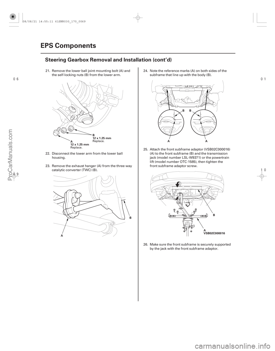
A
12x1.25mm
B
12 x 1.25 mm
A BA
BB
A
A
VSB02C000016 B
21. Remove the lower ball joint mounting bolt (A) and
the self-locking nuts (B) from the lower arm.
22. Disconnect the lower arm from the lower ball housing.
23. Remove the exhaust hanger (A) from the three way catalytic converter (TWC) (B). 24. Note the reference marks (A) on both sides of the
subframe that line up with the body (B).
25. Attach the front subframe adaptor (VSB02C000016) (A) to the front subframe (B) and the transmission
jack (model number LSL-W9371) or the powertrain
lift (model number OTC-1585), then tighten the
front subframe adaptor screw.
26. Make sure the front subframe is securely supported by the jack with the front subframe adaptor.
Replace. Replace.
08/08/21 14:55:11 61SNR030_170_0069
ProCarManuals.com
DYNOMITE -2009-