Page 12 of 104
DESCRIPTION
2-1
2
EAU10410
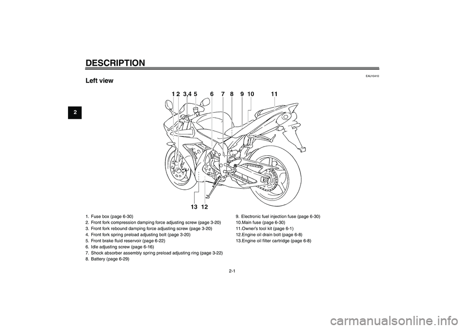
Left view1. Fuse box (page 6-30)
2. Front fork compression damping force adjusting screw (page 3-20)
3. Front fork rebound damping force adjusting screw (page 3-20)
4. Front fork spring preload adjusting bolt (page 3-20)
5. Front brake fluid reservoir (page 6-22)
6. Idle adjusting screw (page 6-16)
7. Shock absorber assembly spring preload adjusting ring (page 3-22)
8. Battery (page 6-29)9. Electronic fuel injection fuse (page 6-30)
10.Main fuse (page 6-30)
11.Owner’s tool kit (page 6-1)
12.Engine oil drain bolt (page 6-8)
13.Engine oil filter cartridge (page 6-8)U5VYE1E0.book Page 1 Tuesday, September 7, 2004 9:09 AM
Page 13 of 104
DESCRIPTION
2-2
2
EAU10420
Right view1. Luggage strap holder (page 3-24)
2. Helmet holder (page 3-20)
3. Passenger seat lock (page 3-19)
4. Rear brake fluid reservoir (page 6-22)
5. Shock absorber assembly compression damping force adjusting screw
(page 3-22)
6. Engine oil filler cap (page 6-8)
7. Air filter element (page 6-14)
8. Engine oil level check window (page 6-8)9. Shock absorber assembly rebound damping force adjusting screw
(page 3-22)
10.Coolant reservoir (page 6-12)
U5VYE1E0.book Page 2 Tuesday, September 7, 2004 9:09 AM
Page 39 of 104

INSTRUMENT AND CONTROL FUNCTIONS
3-25
3
EAU15281
EXUP system This model is equipped with Yamaha’s
EXUP (EXhaust Ultimate Power valve)
system. This system boosts engine
power by means of a valve that regu-
lates the diameter of the exhaust pipe.
The EXUP system valve is constantly
adjusted in accordance with the engine
speed by a computer-controlled servo-
motor.CAUTION:
ECA10191
�
The EXUP system has been set
and extensively tested at the
Yamaha factory. Changing
these settings without sufficient
technical knowledge may result
in poor performance of or dam-
age to the engine.
�
If the EXUP system cannot be
heard when the main switch is
turned on, have a Yamaha deal-er check it.
EAU15300
Sidestand The sidestand is located on the left side
of the frame. Raise the sidestand or
lower it with your foot while holding the
vehicle upright.NOTE:The built-in sidestand switch is part of
the ignition circuit cut-off system, which
cuts the ignition in certain situations.
(See further down for an explanation ofthe ignition circuit cut-off system.)
WARNING
EWA10240
The vehicle must not be ridden with
the sidestand down, or if the side-
stand cannot be properly moved up
(or does not stay up), otherwise the
sidestand could contact the ground
and distract the operator, resulting
in a possible loss of control.
Yamaha’s ignition circuit cut-off
system has been designed to assist
the operator in fulfilling the respon-
sibility of raising the sidestand be-
fore starting off. Therefore, check
this system regularly as describedbelow and have a Yamaha dealer re-
pair it if it does not function proper-
ly.
U5VYE1E0.book Page 25 Tuesday, September 7, 2004 9:09 AM
Page 43 of 104

PRE-OPERATION CHECKS
4-2
4
EAU15603
Pre-operation check list
ITEM CHECKS PAGE
FuelCheck fuel level in fuel tank.
Refuel if necessary.
Check fuel line for leakage.3-17
Engine oilCheck oil level in engine.
If necessary, add recommended oil to specified level.
Check vehicle for oil leakage.6-8
CoolantCheck coolant level in reservoir.
If necessary, add recommended coolant to specified level.
Check cooling system for leakage.6-12
Front brakeCheck operation.
If soft or spongy, have Yamaha dealer bleed hydraulic system.
Check brake pads for wear.
Replace if necessary.
Check fluid level in reservoir.
If necessary, add recommended brake fluid to specified level.
Check hydraulic system for leakage.6-21, 6-22
Rear brakeCheck operation.
If soft or spongy, have Yamaha dealer bleed hydraulic system.
Check brake pads for wear.
Replace if necessary.
Check fluid level in reservoir.
If necessary, add recommended brake fluid to specified level.
Check hydraulic system for leakage.6-21, 6-22
ClutchCheck operation.
Lubricate cable if necessary.
Check lever free play.
Adjust if necessary.6-20
U5VYE1E0.book Page 2 Tuesday, September 7, 2004 9:09 AM
Page 60 of 104

PERIODIC MAINTENANCE AND MINOR REPAIR
6-12
615. Install and tighten the quick fasten-
er screws, and then install the bolt.
EAU20070
Coolant The coolant level should be checked
before each ride. In addition, the cool-
ant must be changed at the intervals
specified in the periodic maintenance
and lubrication chart.
EAU34011
To check the coolant level
1. Place the vehicle on a level sur-
face and hold it in an upright posi-
tion.NOTE:�
The coolant level must be checked
on a cold engine since the level
varies with engine temperature.
�
Make sure that the vehicle is posi-
tioned straight up when checking
the coolant level. A slight tilt to the
side can result in an incorrectreading.
2. Check the coolant level in the cool-
ant reservoir.
NOTE:The coolant should be between theminimum and maximum level marks.3. If the coolant is at or below the
minimum level mark, remove the
brake fluid reservoir bracket bolt,
remove the coolant reservoir cap,
and then add coolant to the maxi-
mum level mark.
1. Slot
2. Projection
1. Maximum level mark
2. Minimum level mark
1. Brake fluid reservoir bracket bolt
U5VYE1E0.book Page 12 Tuesday, September 7, 2004 9:09 AM
Page 61 of 104

PERIODIC MAINTENANCE AND MINOR REPAIR
6-13
6
CAUTION:
ECA10470
�
If coolant is not available, use
distilled water or soft tap water
instead. Do not use hard water
or salt water since it is harmful
to the engine.
�
If water has been used instead
of coolant, replace it with cool-
ant as soon as possible, other-
wise the engine may not be
sufficiently cooled and the cool-
ing system will not be protected
against frost and corrosion.
�
If water has been added to the
coolant, have a Yamaha dealer
check the antifreeze content of
the coolant as soon as possible,
otherwise the effectiveness ofthe coolant will be reduced.WARNING
EWA10380
Never attempt to remove the radiatorcap when the engine is hot.
4. Install the coolant reservoir cap,
and then install the brake fluid res-
ervoir bracket bolt.NOTE:�
The radiator fans are automatically
switched on or off according to the
coolant temperature in the radia-
tor.
�
If the engine overheats, see page6-42 for further instructions.
EAU33030
Changing the coolant
WARNING
EWA10380
Never attempt to remove the radiatorcap when the engine is hot.The coolant must be changed at the in-
tervals specified in the periodic mainte-
nance and lubrication chart. Have a
Yamaha dealer change the coolant.
1. Coolant reservoir capCoolant reservoir capacity (up to the
maximum level mark):
0.25 L (0.26 US qt) (0.22 Imp.qt)
U5VYE1E0.book Page 13 Tuesday, September 7, 2004 9:09 AM
Page 70 of 104

PERIODIC MAINTENANCE AND MINOR REPAIR
6-22
6
EAU22580
Checking the brake fluid level Front brake
Rear brake
Insufficient brake fluid may allow air to
enter the brake system, possibly caus-
ing it to become ineffective.Before riding, check that the brake fluid
is above the minimum level mark and
replenish if necessary. A low brake fluid
level may indicate worn brake pads
and/or brake system leakage. If the
brake fluid level is low, be sure to check
the brake pads for wear and the brake
system for leakage.
Observe these precautions:
�
When checking the fluid level,
make sure that the top of the brake
fluid reservoir is level.
�
Use only the recommended quality
brake fluid, otherwise the rubber
seals may deteriorate, causing
leakage and poor braking perfor-
mance.
�
Refill with the same type of brake
fluid. Mixing fluids may result in a
harmful chemical reaction and
lead to poor braking performance.
�
Be careful that water does not en-
ter the brake fluid reservoir when
refilling. Water will significantly
lower the boiling point of the fluid
and may result in vapor lock.
�
Brake fluid may deteriorate paint-
ed surfaces or plastic parts. Al-
ways clean up spilled fluid
immediately.
�
As the brake pads wear, it is nor-
mal for the brake fluid level to grad-
ually go down. However, if the
brake fluid level goes down sud-
denly, have a Yamaha dealer
check the cause.
1. Minimum level mark
1. Minimum level mark
Recommended brake fluid:
DOT 4
U5VYE1E0.book Page 22 Tuesday, September 7, 2004 9:09 AM
Page 91 of 104

PERIODIC MAINTENANCE AND MINOR REPAIR
6-43
6 Engine overheating
WARNING
EWA10400
�
Do not remove the radiator cap when the engine and radiator are hot. Scalding hot fluid and steam may be
blown out under pressure, which could cause serious injury. Be sure to wait until the engine has cooled.
�
After removing the radiator cap retaining bolt, place a thick rag, like a towel, over the radiator cap, and then
slowly rotate the cap counterclockwise to the detent to allow any residual pressure to escape. When the hissingsound has stopped, press down on the cap while turning it counterclockwise, and then remove the cap.
NOTE:If coolant is not available, tap water can be temporarily used instead, provided that it is changed to the recommended coolantas soon as possible.
Wait until the
engine has cooled.
Check the coolant level in the
reservoir and radiator.
The coolant level
is OK.The coolant level is low.
Check the cooling system
for leakage.
Have a Yamaha dealer checkand repair the cooling system.Add coolant. (See NOTE.)
Start the engine. If the engine overheats again,
have a
Yamaha dealer check
and repair the cooling system.
There is
leakage.
There is
no leakage.
U5VYE1E0.book Page 43 Tuesday, September 7, 2004 9:09 AM