Page 264 of 508
4 - 33
ENGKICK SHAFT, SHIFT SHAFT AND PRIMARY DRIVE GEAR
KICK SHAFT, SHIFT SHAFT AND PRIMARY DRIVE GEAR
PRIMARY DRIVE GEAR
5PAR0008
Extent of removal:
1 Primary drive gear removal
Extent of removal Order Part name Q’ty Remarks
PRIMARY DRIVE GEAR
REMOVAL
Drain the transmission oil. Refer to“TRANSMISSION OIL
REPLACEMENT” section in the CHAP-
TER 3.
Brake pedal
Radiator hose 2 Disconnect at water pump side.
1 Kickstarter crank 1
2 Right crankcase cover 1
3 Primary driven gear 1 Refer to “CLUTCH AND PRIMARY
DRIVEN GEAR” section.
4 Nut (primary drive gear) 1 Refer to “REMOVAL POINTS”.
5Primary drive gear
1
1
Page 276 of 508
4 - 39
ENG
Primary drive gear
1. Install:
�Straight key 1
5PA41160
2. Install:
�Primary drive gear 1
�Conical washer 2
�Nut (primary drive gear) 3
NOTE:
Install the conical washer to the crankshaft 4
as shown in the illustration.
5PA41170
3. Tighten:
�Nut (primary drive gear) 1
Use the drive gear holder 2.
NOTE:
Hold the drive gear holder onto the crankcase
using the M6 bolts 3.
4. Install:
�Primary driven gear
Refer to “CLUTCH AND PRIMARY
DRIVEN GEAR” section.
Drive gear holder:
YM-01495/90890-01495
5PA411801 23
3
T R..79 Nm (7.9 m · kg, 57 ft · lb)
5. Install:
�Dowel pin 1
�Gasket (right crankcase cover) 2
5PA41190
KICK SHAFT, SHIFT SHAFT AND PRIMARY DRIVE GEAR
Page 296 of 508
4 - 49
ENG
EC4M0000
ENGINE REMOVAL
5PA41490
Extent of removal Order Part name Q’ty Remarks
ENGINE REMOVAL
Preparation for removal Hold the machine by placing the
suitable stand under the frame.
WARNING
Support the machine securely so there is no
danger of it falling over.
Drain the coolant. Refer to “COOLANT REPLACEMENT”
section in the CHAPTER 3.
Seat and fuel tank Refer to “SEAT, FUEL TANK AND SIDE
COVERS” section.
Carburetor Refer to “CARBURETOR AND REED
VALVE” section.
Exhaust pipe and silencer Refer to “EXHAUST PIPE AND
SILENCER” section.
Clutch cable Disconnect at engine side.
Radiator hose 1 Disconnect at cylinder head side.
Radiator hose 2 Disconnect at water pump side.
Spark plug cap
Disconnect the CDI magneto
lead.
ENGINE REMOVAL
Page 408 of 508
5 - 41
CHAS
EC5B0000
HANDLEBAR
5PA51290
Extent of removal:
1 Handlebar removal
Extent of removal Order Part name Q’ty Remarks
Preparation for removalHANDLEBAR REMOVAL
Number plate Remove the clamp portion only.
1 Clutch cable 1 Disconnect at the lever side.
2 Clutch lever holder 1
3 Engine stop switch 1
4 Brake master cylinder 1 Refer to “REMOVAL POINTS”.
5 Throttle cable cap 1
6 Grip cap (lower) 1
7 Grip cap (upper) 1
8 Throttle cable 1 Disconnect at the throttle side.
9 Right grip 1 Refer to “REMOVAL POINTS”.
10 Tube guide 1
11 Collar 1
12 Left grip 1 Refer to “REMOVAL POINTS”.
13 Handlebar upper holder 2
14 Handlebar 1
1
HANDLEBAR
Page 416 of 508
5 - 45
CHAS
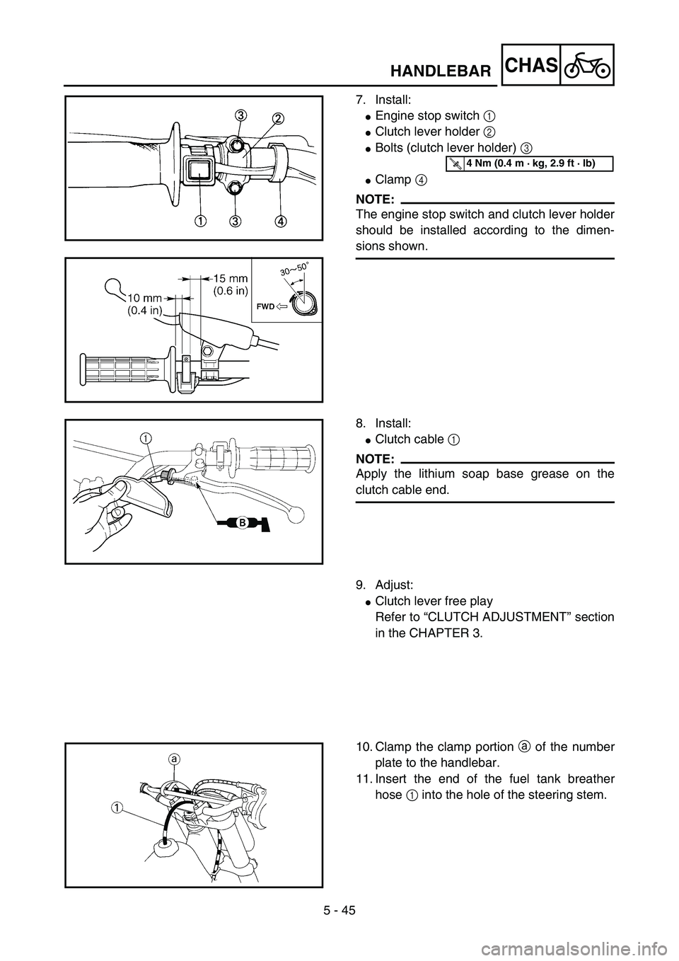
7. Install:
�Engine stop switch 1
�Clutch lever holder 2
�Bolts (clutch lever holder) 3
�Clamp 4
NOTE:
The engine stop switch and clutch lever holder
should be installed according to the dimen-
sions shown.
5PA51420
T R..4 Nm (0.4 m · kg, 2.9 ft · lb)
5PA51430
8. Install:
�Clutch cable 1
NOTE:
Apply the lithium soap base grease on the
clutch cable end.
5PA51440
9. Adjust:
�Clutch lever free play
Refer to “CLUTCH ADJUSTMENT” section
in the CHAPTER 3.
10. Clamp the clamp portion a of the number
plate to the handlebar.
11. Insert the end of the fuel tank breather
hose 1 into the hole of the steering stem.
5PA51450
HANDLEBAR