Page 192 of 508
3 - 35
INSP
ADJ
LUBRICATION
LUBRICATION
To ensure smooth operation of all compo-
nents, lubricate your machine during setup,
after break-in, and after every race.
1All control cable
2Clutch lever pivot
3Shift pedal pivot
4Footrest pivot
5Throttle-to-handlebar contact
6Drive chain
7Tube guide cable winding portion
8Throttle cable end
9Clutch cable endÈUse Yamaha cable lube or equivalent on these
areas.
ÉUse SAE 10W-30 motor oil or suitable chain
lubricants.
ÊLubricate the following areas with high quality,
lightweight lithium-soap base grease.
CAUTION:
Wipe off any excess grease, and avoid get-
ting grease on the brake discs.
AAA
AAB
CC
5PA307705PA307805PA30790
5PA308005PA308105PA30820
5PA308005PA30840
Page 250 of 508
4 - 26
ENGCLUTCH AND PRIMARY DRIVEN GEAR
EC490000
CLUTCH AND PRIMARY DRIVEN GEAR
EC498000
CLUTCH PLATE AND FRICTION PLATE
5PA40720
Extent of removal:
1 Clutch plate and friction plate removal
Extent of removal Order Part name Q’ty Remarks
CLUTCH PLATE AND FRIC-
TION PLATE REMOVAL
Preparation for removal Drain the transmission oil. Refer to “TRANSMISSION OIL
REPLACEMENT” section in the CHAP-
TER 3.
Clutch cable Disconnect at engine side.
1 Clutch cover 1
2 Bolt (clutch spring) 5
3 Clutch spring 5
4 Pressure plate 1
5 Friction plate 7
6 Clutch plate 6
1
Page 252 of 508
4 - 27
ENG
EC498200
PRIMARY DRIVEN GEAR, PUSH ROD AND PUSH LEVER SHAFT
5PAR0006
Extent of removal:
1 Push rod and push lever shaft removal
2 Primary driven gear removal
Extent of removal Order Part name Q’ty Remarks
PRIMARY DRIVEN GEAR,
PUSH ROD AND PUSH LEVER
SHAFT REMOVAL
1 Push rod 1 1
2Ball 1
3 Push rod 2 1
4 Nut (clutch boss) 1
Use special tool.
Refer to “REMOVAL POINTS”. 5 Conical washer 1
6 Clutch boss 1
7 Washer 1
8 Primary driven gear 1
9Spacer 1
10 Washer 1
11 Push lever shaft 1
2
1
1
2
CLUTCH AND PRIMARY DRIVEN GEAR
Page 254 of 508
4 - 28
ENG
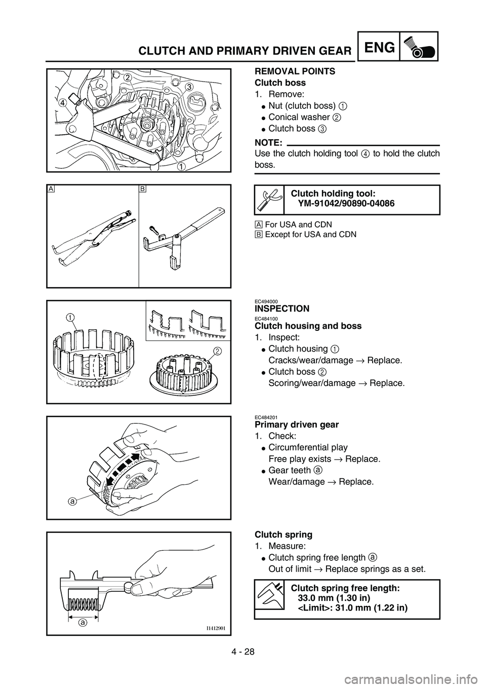
REMOVAL POINTS
Clutch boss
1. Remove:
�Nut (clutch boss) 1
�Conical washer 2
�Clutch boss 3
NOTE:
Use the clutch holding tool 4 to hold the clutch
boss.
ÈFor USA and CDN
ÉExcept for USA and CDN
Clutch holding tool:
YM-91042/90890-04086
5PA40740
ÈÉ
5PA40750
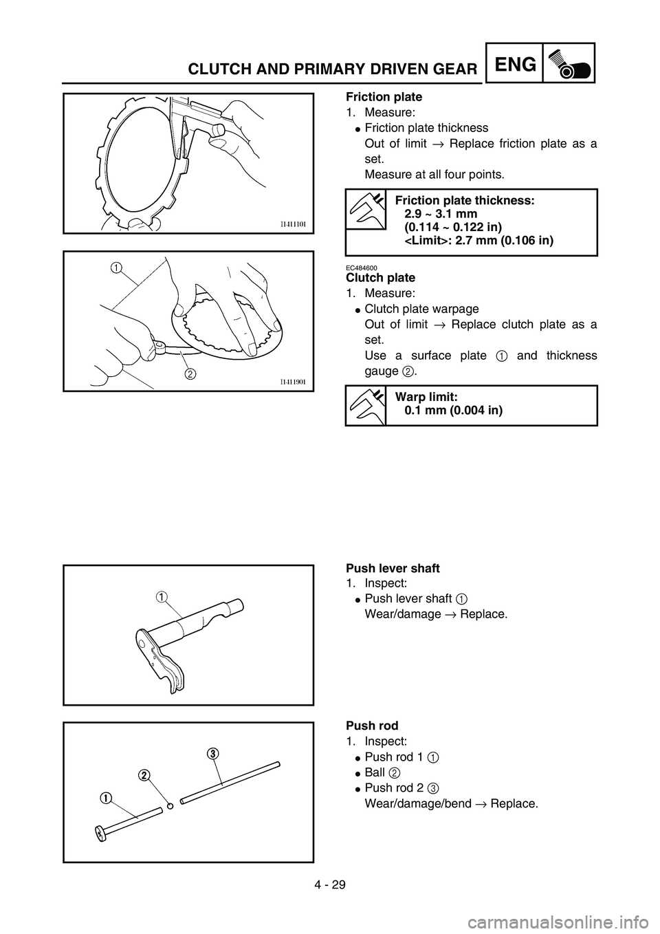
EC494000
INSPECTION
EC484100
Clutch housing and boss
1. Inspect:
�Clutch housing 1
Cracks/wear/damage → Replace.
�Clutch boss 2
Scoring/wear/damage → Replace.
5PA40760
EC484201
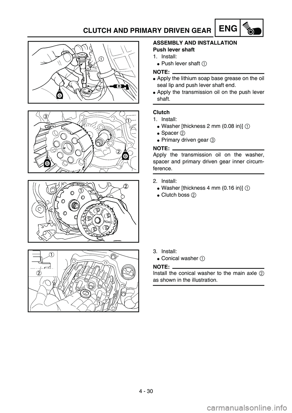
Primary driven gear
1. Check:
�Circumferential play
Free play exists → Replace.
�Gear teeth
a
Wear/damage → Replace.
5PA40770
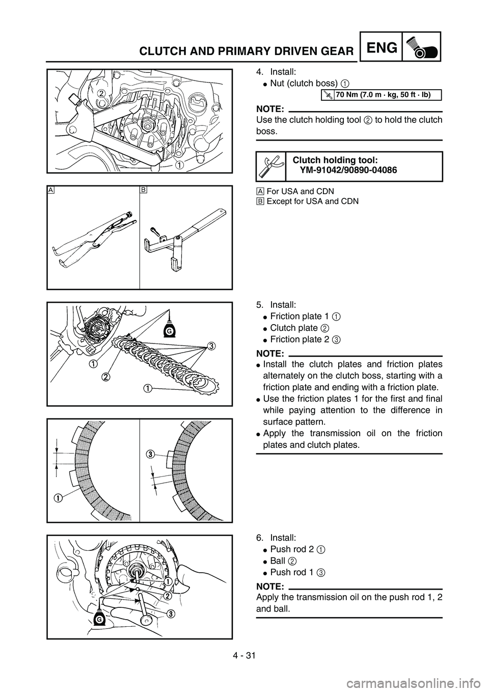
Clutch spring
1. Measure:
�Clutch spring free length
a
Out of limit → Replace springs as a set.
Clutch spring free length:
33.0 mm (1.30 in)
: 31.0 mm (1.22 in)
5PA40780
CLUTCH AND PRIMARY DRIVEN GEAR
Page 256 of 508
4 - 29
ENG
Friction plate
1. Measure:
�Friction plate thickness
Out of limit → Replace friction plate as a
set.
Measure at all four points.
EC484600
Clutch plate
1. Measure:
�Clutch plate warpage
Out of limit → Replace clutch plate as a
set.
Use a surface plate 1 and thickness
gauge 2.
Friction plate thickness:
2.9 ~ 3.1 mm
(0.114 ~ 0.122 in)
: 2.7 mm (0.106 in)
Warp limit:
0.1 mm (0.004 in)
5PA40790
5PA40800
Push lever shaft
1. Inspect:
�Push lever shaft 1
Wear/damage → Replace.
5PA40810
Push rod
1. Inspect:
�Push rod 1 1
�Ball 2
�Push rod 2 3
Wear/damage/bend → Replace.
5PA40820
CLUTCH AND PRIMARY DRIVEN GEAR
Page 258 of 508
4 - 30
ENG
ASSEMBLY AND INSTALLATION
Push lever shaft
1. Install:
�Push lever shaft 1
NOTE:
�Apply the lithium soap base grease on the oil
seal lip and push lever shaft end.
�Apply the transmission oil on the push lever
shaft.5PAR0027
Clutch
1. Install:
�Washer [thickness 2 mm (0.08 in)] 1
�Spacer 2
�Primary driven gear 3
NOTE:
Apply the transmission oil on the washer,
spacer and primary driven gear inner circum-
ference.
2. Install:
�Washer [thickness 4 mm (0.16 in)] 1
�Clutch boss 2
5PAR0007
5PA40850
3. Install:
�Conical washer 1
NOTE:
Install the conical washer to the main axle 2
as shown in the illustration.
5PA40860
CLUTCH AND PRIMARY DRIVEN GEAR
Page 260 of 508
4 - 31
ENG
4. Install:
�Nut (clutch boss) 1
NOTE:
Use the clutch holding tool 2 to hold the clutch
boss.
ÈFor USA and CDN
ÉExcept for USA and CDN
Clutch holding tool:
YM-91042/90890-040865PA40870
T R..70 Nm (7.0 m · kg, 50 ft · lb)
ÈÉ
5PA40880
5. Install:
�Friction plate 1 1
�Clutch plate 2
�Friction plate 2 3
NOTE:
�Install the clutch plates and friction plates
alternately on the clutch boss, starting with a
friction plate and ending with a friction plate.
�Use the friction plates 1 for the first and final
while paying attention to the difference in
surface pattern.
�Apply the transmission oil on the friction
plates and clutch plates.
5PA40890
5PA40900
6. Install:
�Push rod 2 1
�Ball 2
�Push rod 1 3
NOTE:
Apply the transmission oil on the push rod 1, 2
and ball.
5PA40910
CLUTCH AND PRIMARY DRIVEN GEAR
Page 262 of 508
4 - 32
ENG
7. Install:
�Pressure plate 1
NOTE:
Align the punch mark a on the pressure plate
with the punch mark b on the clutch boss.
5PA40920
8. Install:
�Clutch spring 1
�Bolt (clutch spring) 2
NOTE:
Tighten the bolts (clutch spring) in stage, using
a crisscross pattern.
5PA40930
T R..6 Nm (0.6 m · kg, 4.3 ft · lb)
9. Install:
�Dowel pin 1
�Gasket (clutch cover) 2
5PA40940
10. Install:
�Clutch cover 1
�Bolt (clutch cover) 2
NOTE:
Tighten the bolts in stage, using a crisscross
pattern.
5PA40950
T R..10 Nm (1.0 m · kg, 7.2 ft · lb)
CLUTCH AND PRIMARY DRIVEN GEAR