Page 226 of 508
4 - 14
ENGCARBURETOR AND REED VALVE
9. Install:
�Mixing chamber top 1
�Screw (mixing chamber top) 2
To carburetor 3.
NOTE:
�Pass the throttle cable in front of the carbure-
tor breather hoses.
�After installing, check the throttle grip for
smooth movement.5PA40350
Carburetor installation
1. Install:
�Carburetor 1
NOTE:
Install the projection between the carburetor
joint slots.
5PA40360
2. Tighten:
�Screw (air filter joint) 1
�Screw (carburetor joint) 2
5PA40370
3. Clamp:
�Carburetor breather hose 1
�Overflow hose 2
Refer to “CABLE ROUTING DIAGRAM”
section in the CHAPTER 2.
5PA40380
4. Adjust:
�Engine idling speed
Refer to “ENGINE IDLING SPEED
ADJUSTMENT” section in the CHAPTER 3.
Page 227 of 508
 2
sur le carburateur 3.
N.B.:
�Faire p")
4 - 14
ENG
CARBURATEUR ET SOUPAPE FLEXIBLE
VERGASER UND REED-VENTIL
9. Monter:
�Cache de la chambre de carburation 1
�Vis (cache de la chambre de carburation) 2
sur le carburateur 3.
N.B.:
�Faire passer le câble des gaz devant les reniflards
du carburateur.
�Après l’installation, vérifier le mouvement de la
poignée des gaz.
Montage du carburateur
1. Monter:
�Carburateur 1
N.B.:
Veiller à ce que la saillie soit placée entre les fentes
du raccord du carburateur.
2. Serrer:
�Vis (raccord du filtre à air) 1
�Vis (raccord du carburateur) 2
3. Bride:
�Reniflard du carburateur 1
�Durit de trop-plein 2
Se reporter à la section “CHEMINEMENT
DES CABLES” du CHAPITRE 2.
4. Régler:
�Régime de ralenti
Se reporter à la section “REGLAGE DU
REGIME DE RALENTI” du CHAPITRE 3.9. Montieren:
�Mischkammerdeckel 1
�Schraube (Mischkammerdeckel) 2
an den Vergaser 3.
HINWEIS:
�Gasschieberzug vor dem Vergaser-Entlüf-
tungsschlauch vorbeiführen.
�Nach der Montage Gasschieber auf Leicht-
gängigkeit prüfen.
Vergaser montieren
1. Montieren:
�Vergaser 1
HINWEIS:
Die Nase muß sich zwischen den Vergaseran-
schlußschlitzen befinden.
2. Festziehen:
�Schraube (Luftfilteranschluß) 1
�Schraube (Vergaseranschluß) 2
3. Schelle:
�Vergaserlüftungsschlauch 1
�Überlaufschlauch 2
Siehe unter “SEILZUGFÜHRUNG” im
KAPITEL 2.
4. Einstellen:
�Leerlaufdrehzahl
Siehe unter “LEERLAUFDREHZAHL EIN-
STELLEN” im KAPITEL 3.
Page 443 of 508

5 - 58
CHAS
AMORTISSEUR ARRIERE
FEDERBEIN
AMORTISSEUR ARRIERE
Organisation de la dépose:1 Dépose de l’amortisseur arrière2 Démontage de l’amortisseur arrière
Organisation de la dépose Ordre Nom de la pièce QtéRemarques
Préparation à la déposeDEPOSE DE L’AMORTISSEUR
ARRIERE
Caler la moto en plaçant un support
adéquat sous le moteur.
AVERTISSEMENT
Bien caler la moto afin qu’elle ne risque pas de bascu-
ler.
Selle Se reporter à la section “SELLE, RESER-
VOIR DE CARBURANT ET CACHES
LATERAUX” du CHAPITRE 4.
Silencieux Se reporter à la section “TUYAU
D’ECHAPPEMENT ET SILENCIEUX” du
CHAPITRE 4.
1 Bride (raccord du filtre à air) 1 Desserrer uniquement.
2 Cadre arrière 1
3 Boulon (amortisseur arrière - bras
relais)1 Maintenir le bras oscillant.
4 Boulon (amortisseur arrière - cadre) 1
5 Amortisseur arrière 1
6 Contre-écrou 1 Desserrer uniquement.
7 Dispositif de réglage 1 Desserrer uniquement.
8 Guide de ressort 1
9 Ressort (amortisseur arrière) 1
1
2
FEDERBEIN
Demontage-Arbeiten:
1 Federbein
2 Federbein zerlegen
Demontage-Arbeiten
Reihen-
folgeBezeichnung Anz. Bemerkungen
Vorbereitung für die
DemontageHINTEREN STOSSDÄMPFER
ABBAUEN
Das Motorrad auf einem geeigne-
ten Ständer unter den Motor auf-
bocken.
WARNUNG
Das Motorrad gegen Umfallen sichern.
Sitzbank Siehe unter “SITZBANK, KRAFTSTOFF-
TANK UND SEITENABDECKUNGEN” in
KAPITEL 4.
Schalldämpfer Siehe unter “KRÜMMER UND SCHALL-
DÄMPFER” in KAPITEL 4.
1 Schlauchschelle (Luftfilteran-
schluß)1 nur lockern.
2 Rahmenhinterteil 1
3 Schraube (Federbein-Umlenkhebel) 1 Schwinge festhalten.
4 Schraube (Federbein-Rahmen) 1
5 Federbein 1
6 Sicherungsmutter 1 nur lockern.
7 Einstellmutter 1 nur lockern.
8 Federsitz 1
9 Feder (Federbein) 1
1
2
Page 450 of 508
5 - 62
CHAS
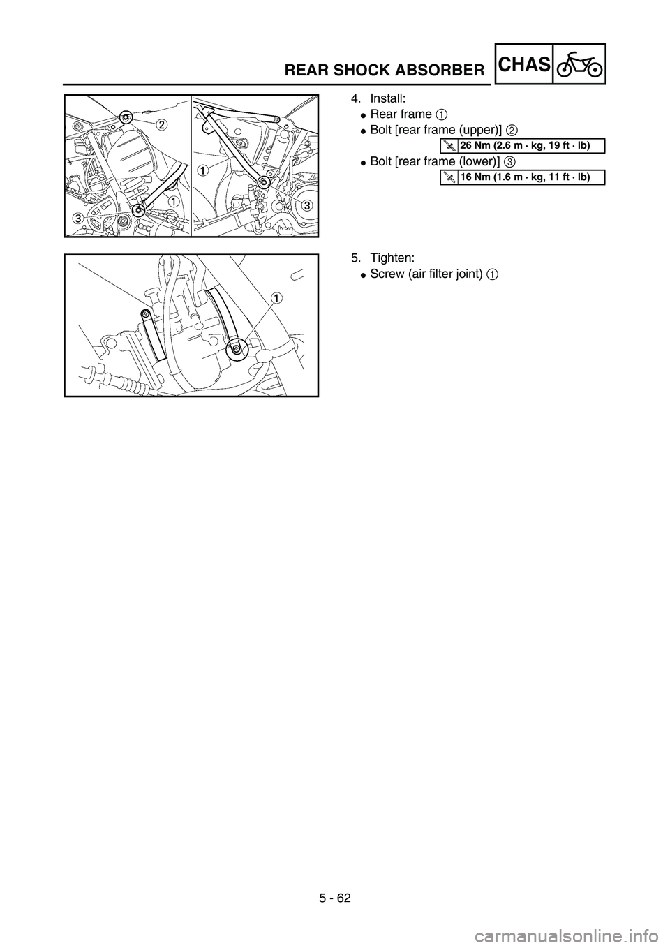
4. Install:
�Rear frame 1
�Bolt [rear frame (upper)] 2
�Bolt [rear frame (lower)] 3
5PA51960
T R..26 Nm (2.6 m · kg, 19 ft · lb)
T R..16 Nm (1.6 m · kg, 11 ft · lb)
5. Tighten:
�Screw (air filter joint) 1
5PA51970
REAR SHOCK ABSORBER
Page 451 of 508
5 - 62
CHAS
4. Monter:
�Cadre arrière 1
�Boulon [cadre arrière (supérieur)] 2
�Boulon [cadre arrière (inférieur)] 3
T R..26 Nm (2,6 m · kg, 19 ft · lb)
T R..16 Nm (1,6 m · kg, 11 ft · lb)
5. Serrer:
�Vis (raccord du filtre à air) 1
AMORTISSEUR ARRIERE
FEDERBEIN
4. Montieren:
�Rahmen-Hinterteil 1
�Schraube (oberes Rahmen-Hinterteil) 2
�Schraube (unteres Rahmen-Hinterteil) 3
T R..26 Nm (2,6 m · kg, 19 ft · lb)
T R..16 Nm (1,6 m · kg, 11 ft · lb)
5. Festziehen:
�Schraube (Luftfilteranschluß) 1
Page 476 of 508

7 - 7
TUN
Road condition and examples of carburetor setting
NOTE:
Optimum pilot air screw setting can be obtained by adding the ex-factory number of the same screw
back-out turns to any required value provided in the chart.
For example, if the ex-factory number is “2”, add “2” to the value chosen in the chart.
Examples of carburetor setting depending on symptomConditions
PartsGeneral condition Sandy condition
Under 10 °C
(50 °F)
(Winter)15 ~ 25 °C
(59 ~ 77 °F)
(Spring, Autumn)
Over 30 °C
(86 °F)
(Summer)Under 10 °C
(50 °F)
(Winter)15 ~ 25 °C
(59 ~ 77 °F)
(Spring, Autumn)
Over 30 °C
(86 °F)
(Summer)
Main jet #140 #138 #135 ~ #138 #142 #142 #142
Jet needle NBKF-2 NBKF-2 NBKF-2 NBKF-2 NBKF-2 NBKF-2
Pilot jet #45 #45 #45 #48 #48 #48
Pilot air screw Zero Zero +1/4–1/2–1/2 Zero ~ +1/2
Symptom Setting Checking
At full throttle
Stall at high speeds
*Hard breathing
Shearing noise
Whitish spark plug
Lean mixtureIncrease main jet calibration no.
(Gradually)Discoloration of spark plug →
If tan color, it is in good condition.
If cannot be corrected:
Clogged float valve seat
Clogged fuel hose
Clogged fuel cock
At full throttle
Speed pick-up stops
Slow speed pick-up
Slow response
Sooty spark plug
Rich mixtureDecrease main jet calibration no.
(Gradually)
*In case of racing slight enrich-
ment of mixture reduces engine
trouble.Discoloration of spark plug →
If tan color, it is in good condition.
If cannot be corrected:
Clogged air filter
Fuel overflow from carburetor
Lean mixture Use jet needle with a smaller
diameter, or NBLF.
Lower jet needle clip position.
The clip position is the jet needle
groove on which the clip is
installed. The positions are num-
bered from the top. Rich mixture Use jet needle with a larger diam-
eter, or NBKG.
Raise jet needle clip position.
1/4 ~ 3/4 throttle
*Hard breathing
Lack of speedUse jet needle with a smaller
diameter, or NBLF.
Lower jet needle clip position.
1/4 ~ 1/2 throttle
Slow speed pick-up
White smoke
Poor accelerationUse jet needle with a larger diam-
eter, or NBKG.
Raise jet needle clip position.
Closed to 1/4 throttle
*Hard breathing
Speed downUse jet needle with a smaller
diameter.
Turn out pilot air screw.
Leaner
↑(Standard)
↓
Richer
SETTING
Page 477 of 508

7 - 8
TUN
* marked: In case of hard breathing, check the carburetor breather hoses for clogging. Closed to 1/4 throttle
Poor acceleration
White smokeUse jet needle with a larger diam-
eter.
Turn in pilot air screw.
Unstable at low speeds
Pinking noiseLower jet needle clip position.
(1 groove down)
Turn in pilot air screw.
Poor response at
extremely low speedReduce pilot jet calibration No.
Turn out pilot air screw.
If not effect, reverse the above
procedures.Dragging brake
Overflow from carburetor
Poor response in the low
to intermediate speedsRaise jet needle clip position.
If this has no effect, lower the jet
needle clip position.
Poor response when
throttle is opened quicklyCheck overall settings.
Use main jet with a lower calibra-
tion no.
Raise jet needle clip position.
Use jet needle with a larger diam-
eter.
If these have no effect, use a main
jet with a higher calibration no.
and lower the jet needle clip posi-
tion.Check air filter for fouling.
Poor engine operation Turn in pilot air screw.
Adjust the throttle stop screw.Check throttle valve operation. Symptom Setting Checking
This should be taken simply for an example. It
is necessary to set the carburetor while check-
ing the operating conditions of the engine and
discoloration of spark plugs.
Normally, carburetor setting is made by means
of the main jet, jet needle clip position, pilot jet
and pilot air screw.
SETTING
Page:
< prev 1-8 9-16 17-24