Page 121 of 508

3 - 2
INSP
ADJ
MAINTENANCE INTERVALS
COOLING SYSTEM
Check coolant level and leakage
Check radiator cap operation
Replace coolant
Inspect hoses
��
��
�
Every two years
OUTSIDE NUTS AND BOLTS
Retighten
��
AIR FILTER
Clean and lubricate
Replace
��
�Use foam air-filter oil or
equivalent oil
FRAME
Clean and inspect
��
FUEL TANK, COCK
Clean and inspect
��
BRAKES
Adjust lever position and pedal height
Lubricate pivot point
Check brake disc surface
Check fluid level and leakage
Retighten brake disc bolts, caliper
bolts, master cylinder bolts and union
bolts
Replace pads
Replace brake fluid
�
�
�
�
��
�
�
�
�
�
�
Every one year
FRONT FORKS
Inspect and adjust
Replace oil
Replace oil seal
�
��
�
�
Suspension oil “01”
FRONT FORK OIL SEAL AND DUST
SEAL
Clean and lube
��Lithium base grease
REAR SHOCK ABSORBER
Inspect and adjust
Lube
Retighten
�
��
��(After
rain ride)
�
Molybdenum disulfide
grease
DRIVE CHAIN GUIDE, ROLLERS AND
SUPPORT
Inspect
�
SWINGARM
Inspect and retighten
Lube
�
��
�
Molybdenum disulfide
grease
RELAY ARM, CONNECTING ROD
Inspect and retighten
Lube
�
��
�
Molybdenum disulfide
grease
STEERING HEAD
Inspect free play and retighten
Clean and lube
Replace bearing
��
�
�
Lithium base grease ItemAfter
break-inEvery
raceEvery
third
raceEvery
fifth
raceAs re-
quiredRemarks
3
Page 129 of 508

3 - 4
INSP
ADJ
PRE-OPERATION INSPECTION AND MAINTENANCE
EC320000
PRE-OPERATION INSPECTION AND MAINTENANCE
Before riding for break-in operation, practice or a race, make sure the machine is in good operating
condition.
Before using this machine, check the following points.
GENERAL INSPECTION AND MAINTENANCE
Item Routine Page
CoolantCheck that coolant is filled up to the radiator cap.
Check the cooling system for leakage.P.3-5 ~ 9
FuelCheck that a fresh mixture of oil and gasoline is filled in the fuel
tank. Check the fuel line for leakage.P.1-13
Transmission oilCheck that the oil level is correct. Check the crankcase for leak-
age.P.3-12 ~ 13
Gear shifter and clutchCheck that gears can be shifted correctly in order and that the
clutch operates smoothly.P.3-9
Throttle grip/HousingCheck that the throttle grip operation and free play are correctly
adjusted. Lubricate the throttle grip and housing, if necessary.P.3-10
Brakes Check the play of front brake and effect of front and rear brake. P.3-16 ~ 21
Drive chainCheck drive chain slack and alignment. Check that the drive
chain is lubricated properly.P.3-22 ~ 24
WheelsCheck for excessive wear and tire pressure. Check for loose
spokes and have no excessive play.P.3-31 ~ 32
SteeringCheck that the handlebar can be turned smoothly and have no
excessive play.P.3-32 ~ 34
Front forks and rear shock
absorberCheck that they operate smoothly and there is no oil leakage. P.3-24 ~ 30
Cables (wires)Check that the clutch and throttle cables move smoothly. Check
that they are not caught when the handlebars are turned or
when the front forks travel up and down.—
Exhaust pipe and silencerCheck that the exhaust pipe is tightly mounted and has no
cracks.P.4-2
Rear wheel sprocket Check that the rear wheel sprocket tightening bolt is not loose. P.3-22
Lubrication Check for smooth operation. Lubricate if necessary. P.3-35
Bolts and nuts Check the chassis and engine for loose bolts and nuts. P.1-17
Lead connectorsCheck that the CDI magneto, CDI unit, and ignition coil are con-
nected tightly.P.1-6
SettingsIs the machine set suitably for the condition of the racing course
and weather or by taking into account the results of test runs
before racing? Are inspection and maintenance completely
done?P.7-1 ~ 19
Page 186 of 508
3 - 32
INSP
ADJ
EC36T000
WHEEL INSPECTION
1. Inspect:
�Wheel runout
Elevate the wheel and turn it.
Abnormal runout → Replace.
5PA30700
2. Inspect:
�Bearing free play
Exist play → Replace.
5PA30710
STEERING HEAD INSPECTION AND
ADJUSTMENT
1. Elevate the front wheel by placing a suit-
able stand under the engine.
2. Check:
�Steering stem
Grasp the bottom of the forks and gently
rock the fork assembly back and forth.
Free play → Adjust steering head.
3. Check:
�Steering smooth action
Turn the handlebar lock to lock.
Unsmooth action → Adjust steering ring
nut.
5PA30720
5PA30730
WHEEL INSPECTION/
STEERING HEAD INSPECTION AND ADJUSTMENT
Page 188 of 508
3 - 33
INSP
ADJ
STEERING HEAD INSPECTION AND ADJUSTMENT
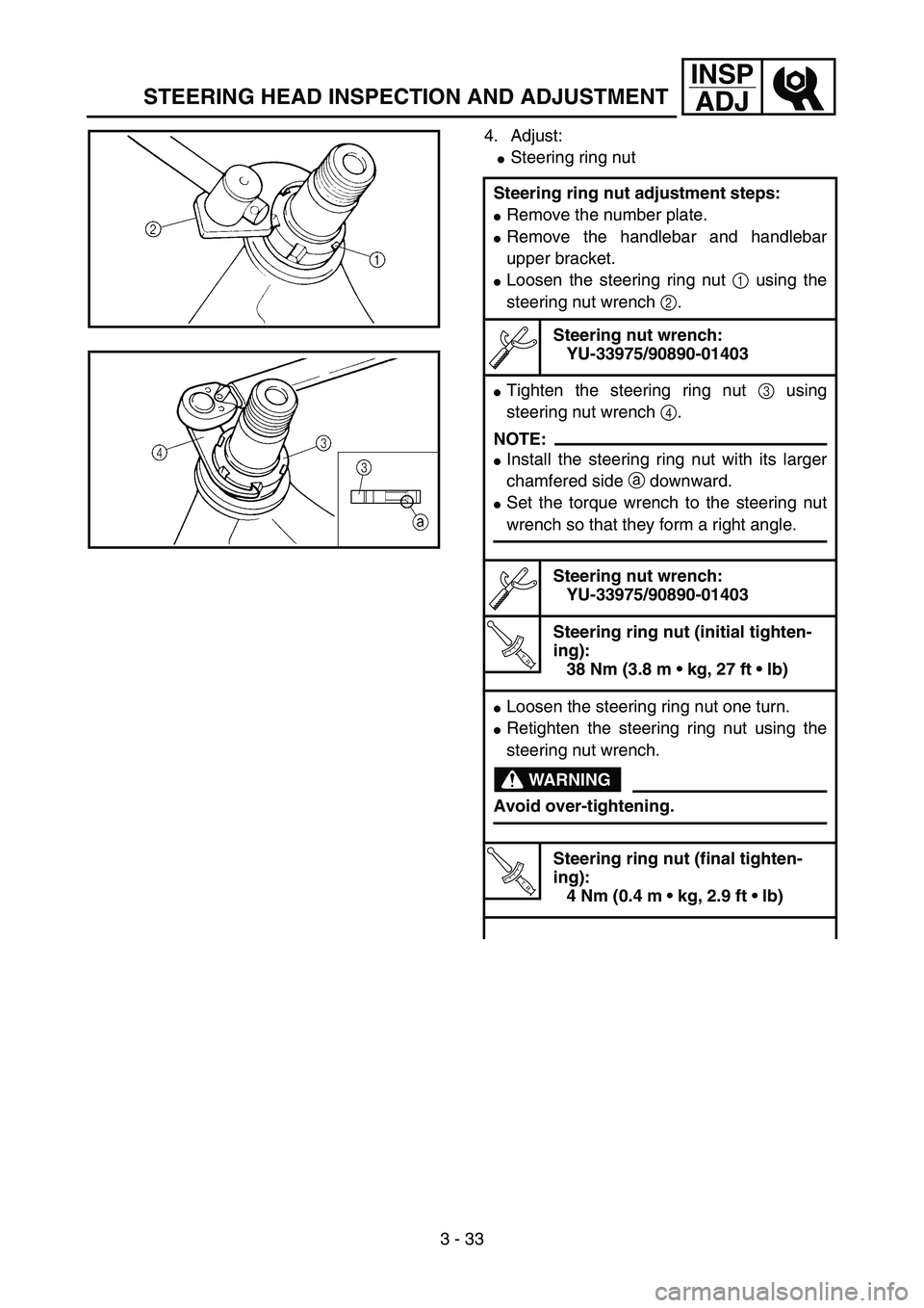
4. Adjust:
�Steering ring nut
Steering ring nut adjustment steps:
�Remove the number plate.
�Remove the handlebar and handlebar
upper bracket.
�Loosen the steering ring nut 1 using the
steering nut wrench 2.
Steering nut wrench:
YU-33975/90890-01403
�Tighten the steering ring nut 3 using
steering nut wrench 4.
NOTE:
�Install the steering ring nut with its larger
chamfered side a downward.
�Set the torque wrench to the steering nut
wrench so that they form a right angle.
Steering nut wrench:
YU-33975/90890-01403
T R..
Steering ring nut (initial tighten-
ing):
38 Nm (3.8 m kg, 27 ft lb)
�Loosen the steering ring nut one turn.
�Retighten the steering ring nut using the
steering nut wrench.
WARNING
Avoid over-tightening.
T R..
Steering ring nut (final tighten-
ing):
4 Nm (0.4 m kg, 2.9 ft lb)
5PA30740
5PA30740
Page 190 of 508
3 - 34
INSP
ADJ
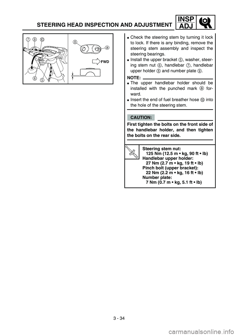
�Check the steering stem by turning it lock
to lock. If there is any binding, remove the
steering stem assembly and inspect the
steering bearings.
�Install the upper bracket 5, washer, steer-
ing stem nut 6, handlebar 7, handlebar
upper holder 8 and number plate 9.
NOTE:
�The upper handlebar holder should be
installed with the punched mark a for-
ward.
�Insert the end of fuel breather hose 0 into
the hole of the steering stem.
CAUTION:
First tighten the bolts on the front side of
the handlebar holder, and then tighten
the bolts on the rear side.
T R..
Steering stem nut:
125 Nm (12.5 m kg, 90 ft lb)
Handlebar upper holder:
27 Nm (2.7 m kg, 19 ft lb)
Pinch bolt (upper bracket):
22 Nm (2.2 m kg, 16 ft lb)
Number plate:
7 Nm (0.7 m kg, 5.1 ft lb)
5PA30760
STEERING HEAD INSPECTION AND ADJUSTMENT
Page 416 of 508
5 - 45
CHAS
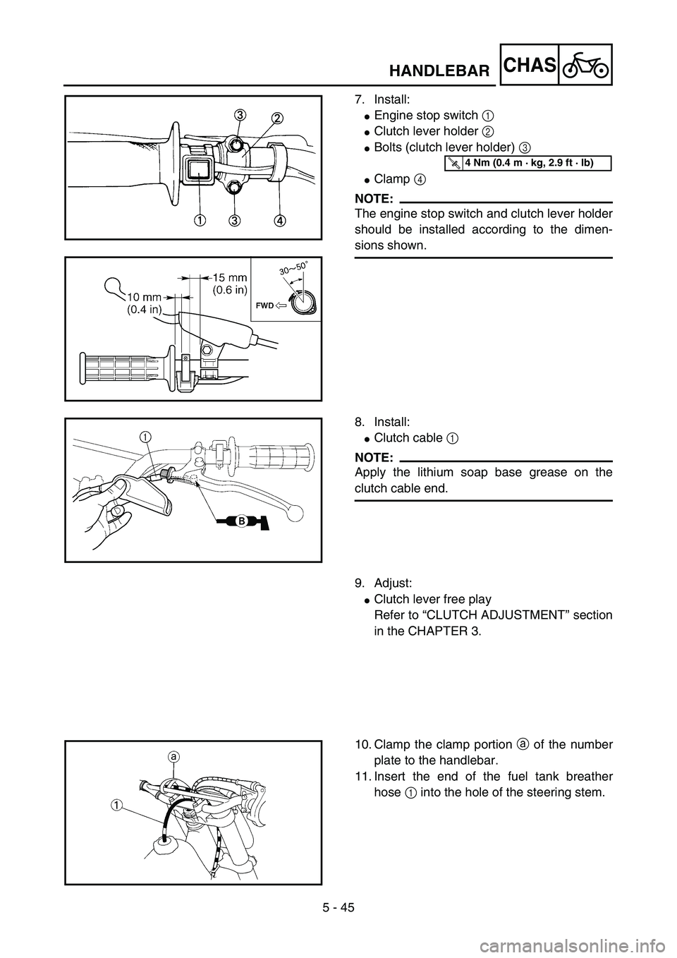
7. Install:
�Engine stop switch 1
�Clutch lever holder 2
�Bolts (clutch lever holder) 3
�Clamp 4
NOTE:
The engine stop switch and clutch lever holder
should be installed according to the dimen-
sions shown.
5PA51420
T R..4 Nm (0.4 m · kg, 2.9 ft · lb)
5PA51430
8. Install:
�Clutch cable 1
NOTE:
Apply the lithium soap base grease on the
clutch cable end.
5PA51440
9. Adjust:
�Clutch lever free play
Refer to “CLUTCH ADJUSTMENT” section
in the CHAPTER 3.
10. Clamp the clamp portion a of the number
plate to the handlebar.
11. Insert the end of the fuel tank breather
hose 1 into the hole of the steering stem.
5PA51450
HANDLEBAR
Page 418 of 508
5 - 46
CHAS
EC560000
STEERING
5PAR0017
Extent of removal:
1 Lower bracket removal
2 Bearing removal
Extent of removal Order Part name Q’ty Remarks
STEERING REMOVAL
WARNING
Support the machine securely so there is no
danger of it falling over.
Refer to “HANDLEBAR” section. Preparation for removal Hold the machine by placing the
suitable stand under the engine.
Number plate
Handlebar
Cable guide
Front fender
1 Steering stem nut 1
2 Front fork 2 Refer to “FRONT FORK” section.
3 Upper bracket 1
4 Steering ring nut 1 Use special tool.
Refer to “REMOVAL POINTS”.
5 Lower bracket 1
6 Bearing race cover 1
7 Upper bearing 1
8 Lower bearing 1 Refer to “REMOVAL POINTS”.
9 Bearing race 2 Refer to “REMOVAL POINTS”.
2
1
STEERING
Page 420 of 508
5 - 47
CHAS
EC563000
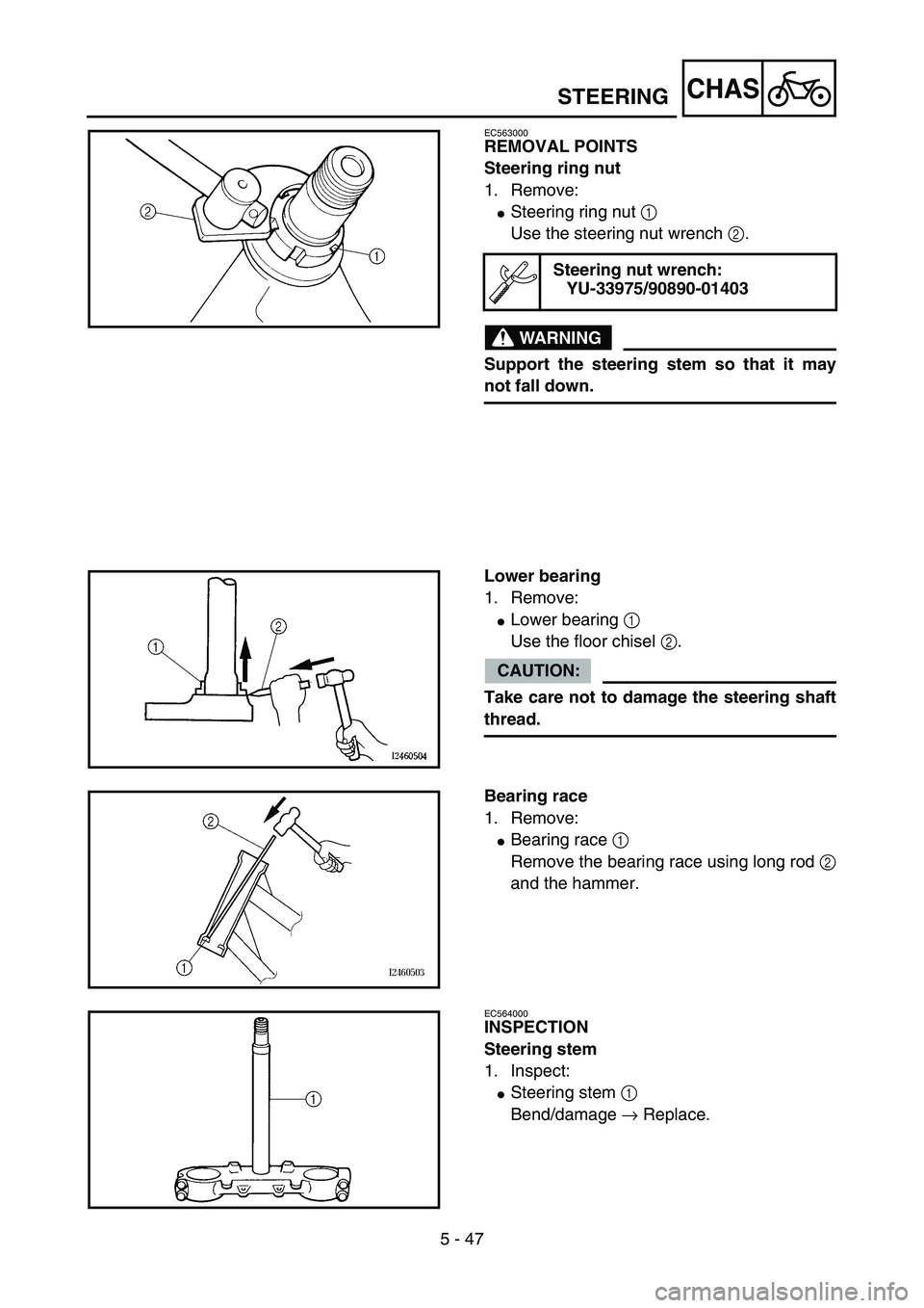
REMOVAL POINTS
Steering ring nut
1. Remove:
�Steering ring nut 1
Use the steering nut wrench 2.
WARNING
Support the steering stem so that it may
not fall down.
Steering nut wrench:
YU-33975/90890-01403
5PA51470
Lower bearing
1. Remove:
�Lower bearing 1
Use the floor chisel 2.
CAUTION:
Take care not to damage the steering shaft
thread.
5PA51480
Bearing race
1. Remove:
�Bearing race 1
Remove the bearing race using long rod 2
and the hammer.
5PA51490
EC564000
INSPECTION
Steering stem
1. Inspect:
�Steering stem 1
Bend/damage → Replace.
5PA51500
STEERING