Page 164 of 364
3 - 19
INSP
ADJ
LUBRICATION
LUBRICATION
To ensure smooth operation of all compo-
nents, lubricate your machine during setup,
after break-in, and after every race.
1All control cable
2Brake lever pivot
3Shift pedal pivot
4Footrest pivot
5Throttle-to-handlebar contact
6Drive chain
7Tube guide cable winding portion
8Throttle cable end
9Brake cable endÅUse Yamaha cable lube or equivalent on these
areas.
ıUse SAE 10W-30 motor oil or suitable chain
lubricants.
ÇLubricate the following areas with high quality,
lightweight lithium-soap base grease.
AAA
AAB
CC
78
Page 168 of 364

WARNING
Batteries generate explosive hydrogen gas
and contain electrolyte which is made of
poisonous and highly caustic sulfuric acid.
There")
3 - 21
INSP
ADJ
BATTERY INSPECTION AND CHARGING
(TT-R90E)
WARNING
Batteries generate explosive hydrogen gas
and contain electrolyte which is made of
poisonous and highly caustic sulfuric acid.
Therefore, always follow these preventive
measures:
�Wear protective eye gear when handling
or working near batteries.
�Charge batteries in a well-ventilated area.
�Keep batteries away from fire, sparks or
open flames (e.g., welding equipment,
lighted cigarettes).
�DO NOT SMOKE when charging or han-
dling batteries.
�KEEP BATTERIES AND ELECTROLYTE
OUT OF REACH OF CHILDREN.
�Avoid bodily contact with electrolyte as it
can cause severe burns or permanent eye
injury.
FIRST AID IN CASE OF BODILY CONTACT:
EXTERNAL
�Skin — Wash with water.
�Eyes — Flush with water for 15 minutes
and get immediate medical attention.
INTERNAL
�Drink large quantities of water or milk fol-
lowed with milk of magnesia, beaten egg
or vegetable oil. Get immediate medical
attention.
CAUTION:
Charging time, charging amperage and
charging voltage for an MF battery are dif-
ferent from those of conventional batteries.
The MF battery should be charged as
explained in the charging method illustra-
tions. If the battery is overcharged, the
electrolyte level will drop considerably.
Therefore, take special care when charging
the battery.
BATTERY INSPECTION AND CHARGING (TT-R90E)
Page 183 of 364

INSP
ADJ
6. Montieren:
�Batterie
7. Kontrollieren:
�Batteriepole
Verschmutzt → Mit einer Messing-
Drahtbürste säubern.
Lose → Fest verbinden.
8. Schmieren:
�Batteriepole
9. Anschließen:
�Batterie-Leitungsstecker
(an die Batteriepole)
10. Montieren:
�Hinteres Schutzblech
�Sitzbank
Empfohlenes Schmiermittel:
Lithiumfett
SICHERUNGEN KONTROLLIEREN
(TT-R90E)
ACHTUNG:
Vor Überprüfung oder Austausch einer
Sicherung immer das Zündschloß auf
“OFF” stellen, um einen Kurzschluß zu ver-
meiden.
1. Demontieren:
�Sitzbank
�Hinteres Schutzblech
2. Kontrollieren:
�Durchgang
2Sicherung umkehren
Abeitsschritte:
�Die Sicherung 1 entfernen
�Das Taschen-Multimeter an die Sicherung
anschließen und diese auf Durchgang
prüfen.
HINWEIS:
Den Wahlschalter des Taschen-Multime-
ters auf “Ω × 1” stellen.
Taschen-Multimeter:
YU-03112-C/90890-03112
�Falls das Multimeter “∞” anzeigt, die
Sicherung erneuern.
INSPECTION DES FUSIBLES (TT-R90E)
SICHERUNGEN KONTROLLIEREN (TT-R90E)
6. Monter:
�Batterie
7. Contrôler:
�Bornes de batterie
Crasse → Nettoyer avec une brosse à poils
métalliques.
Connexions lâches → Serrer correctement.
8. Lubrifier:
�Bornes de batterie
9. Connecter:
�Raccord de fil de batterie
(aux bornes de la batterie)
10. Monter:
�Aile arrière
�Selle
Lubrifiant recommandé:
Graisse à base de savon de lithium
INSPECTION DES FUSIBLES (TT-R90E)
ATTENTION:
Pour éviter un court -circuit, toujours placer le
contacteur à clé sur “OFF” avant de contrôler
ou de remplacer un fusible.
1. Déposer:
�Selle
�Aile arrière
2. Contrôler:
�Continuité
2Fusible inversé
Etapes de la vérification:
�Depose du fusible 1
�Connecter le multimètre au fusible et contrôler
la continuité du circuit.
N.B.:
Régler le sélecteur du multimètre sur “Ω × 1”.
Multimètre:
YU-03112-C/90890-03112
�Si le multimètre indique “∞”, remplacer le
fusible.
3 - 27
Page 206 of 364

4 - 11
ENGCYLINDER HEAD
4. Remove:
�Cylinder head
NOTE:
�Loosen the bolts and nuts in their proper
loosening sequence.
�Start by loosening each bolt and nut 1/2 turn
until all are loose.
ASSEMBLY AND INSTALLATION
1. Install:
�Cylinder head
2. Tighten:
�Nuts
�Bolts
NOTE:
�Apply the engine oil on the contact surfaces
of the nuts, bolts and copper washers.
�Follow the numerical order shown in the illus-
tration. Tighten the bolts and nuts in two
stages.
T R..22 Nm (2.2 m · kg, 16 ft · lb)
T R..10 Nm (1.0 m · kg, 7.2 ft · lb)
3. Install:
�Camshaft sprocket 1
Installation steps:
�Turn the crankshaft counterclockwise until
the “I” mark a on the rotor is aligned with
the stationary pointer b on the crankcase
cover.
�Align the “I” mark c on the camshaft
sprocket with the stationary pointer d on
the cylinder head.
�Fit the timing chain 2 onto camshaft
sprocket and install the camshaft sprocket
on the camshaft.
NOTE:
When installing the camshaft sprocket, keep
the timing chain as tense as possible on the
exhaust side.
Page 212 of 364
4 - 14
ENGCAMSHAFT AND ROCKER ARMS
REMOVAL POINTS
Rocker arm shaft
1. Remove:
�Rocker arm shafts
NOTE:
Use a slide hammer bolt 1 and weight 2 to
slide out the rocker arm shafts.
Slide hammer set:
YU-1083-A
Slide hammer bolt:
90890-01085
Weight:
90890-01084
INSPECTION
Camshaft
1. Measure:
�Cam lobes length a and b
Out of specification → Replace.
Cam lobes length limit:
Intake:
a 25.398 mm (0.9999 in)
b 21.004 mm (0.8269 in)
Exhaust:
a 25.256 mm (0.9943 in)
b 21.017 mm (0.8274 in)
ASSEMBLY AND INSTALLATION
1. Apply:
�Molybdenum disulfide oil
(onto the camshaft cam lobe)
�Engine oil
(onto the camshaft bearing)
2. Install:
�Camshaft 1
Page 214 of 364
4 - 15
ENGCAMSHAFT AND ROCKER ARMS
3. Apply:
�Molybdenum disulfide oil
(onto the rocker arm and rocker arm
shaft)
4. Install:
�Rocker arm 1
�Rocker arm shaft 2
Page 222 of 364

4 - 19
ENGVALVES AND VALVE SPRINGS
2. Lap:
�Valve face
�Valve seat
NOTE:
After refacing the valve seat or replacing the
valve and valve guide, the valve seat and
valve face should be lapped.
Lapping steps:
�Apply a coarse lapping compound to the
valve face.
CAUTION:
Do not let the compound enter the gap
between the valve stem and the guide.
�Apply molybdenum disulfide oil to the
valve stem.
�Install the valve into the cylinder head.
�Turn the valve until the valve face and
valve seat are evenly polished, then clean
off all of the compound.
NOTE:
For best lapping results, lightly tap the valve
seat while rotating the valve back and forth
between your hands.
�Apply a fine lapping compound to the
valve face and repeat the above steps.
NOTE:
After every lapping operation be sure to
clean off all of the compound from the valve
face and valve seat.
�Apply Mechanic’s blueing dye (Dykem) to
the valve face.
�Install the valve into the cylinder head.
�Press the valve through the valve guide
and onto the valve seat to make a clear
pattern.
�Measure the valve seat width again. If the
valve seat width is out of specification,
reface and relap the valve seat.
Page 224 of 364
4 - 20
ENGVALVES AND VALVE SPRINGS
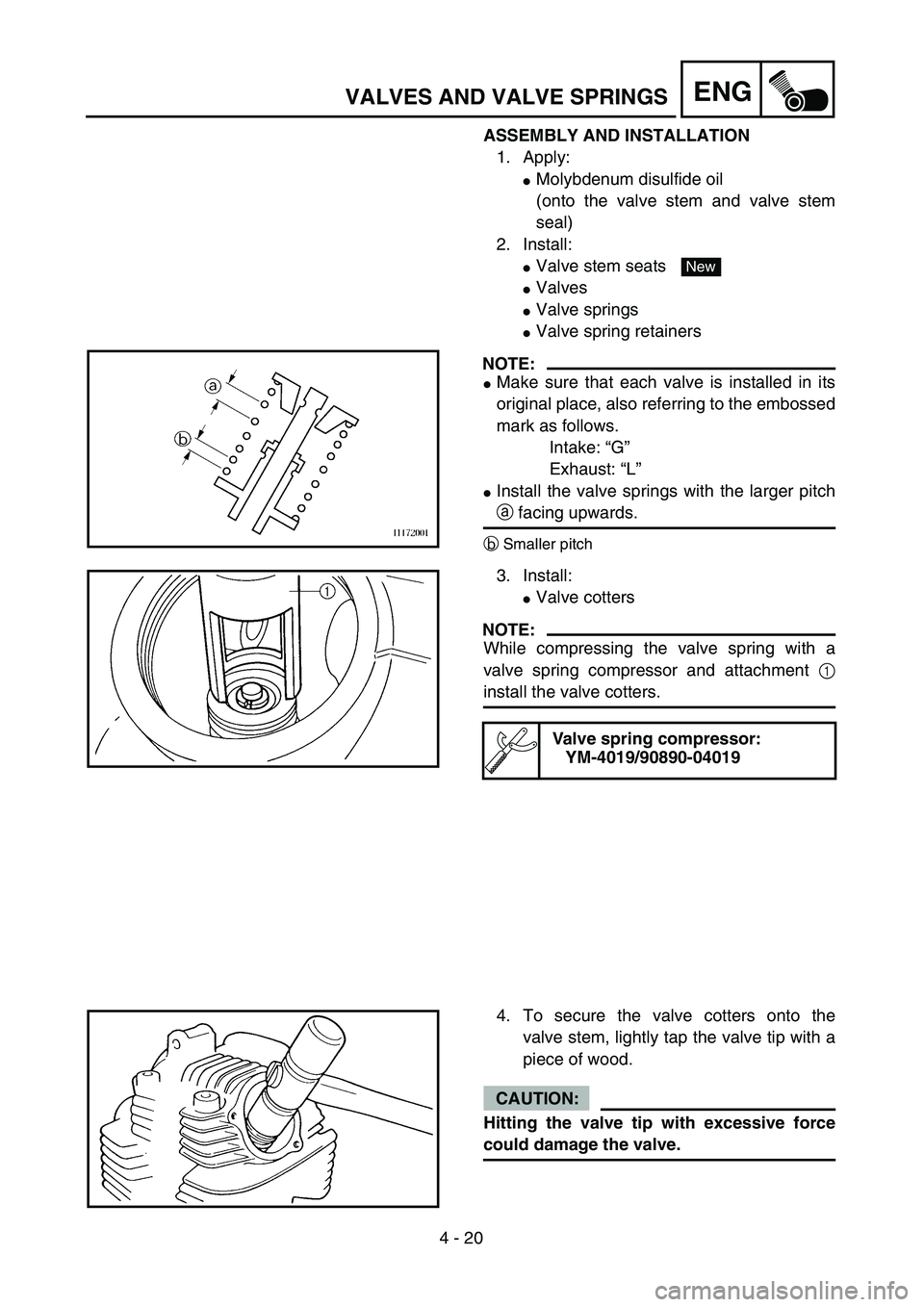
ASSEMBLY AND INSTALLATION
1. Apply:
�Molybdenum disulfide oil
(onto the valve stem and valve stem
seal)
2. Install:
�Valve stem seats
�Valves
�Valve springs
�Valve spring retainers
NOTE:
�Make sure that each valve is installed in its
original place, also referring to the embossed
mark as follows.
Intake: “G”
Exhaust: “L”
�Install the valve springs with the larger pitch
a facing upwards.
bSmaller pitch
New
3. Install:
�Valve cotters
NOTE:
While compressing the valve spring with a
valve spring compressor and attachment 1
install the valve cotters.
Valve spring compressor:
YM-4019/90890-04019
4. To secure the valve cotters onto the
valve stem, lightly tap the valve tip with a
piece of wood.
CAUTION:
Hitting the valve tip with excessive force
could damage the valve.