Page 57 of 90

PERIODIC MAINTENANCE AND MINOR REPAIR
6-13
2
3
4
5
67
8
9
check for the cause.
10. Turn the engine off, and then
check the oil level and correct it if
necessary.
11. Reset the oil change indicator ac-
cording to the following procedure.
To reset the oil change indicator
1. Turn the key to “ON”.
2. Hold the “OIL CHANGE” button
pushed for two to eight seconds.
3. Release the “OIL CHANGE” but-
ton, and the oil change indicator
will go off.
NOTE:
If the engine oil is changed before the
oil change indicator comes on (i.e. be-fore the periodic oil change interval has
been reached), the indicator must be
reset after the oil change for the next
periodic oil change to be indicated at
the correct time. To reset the oil change
indicator before the periodic oil change
interval has been reached, follow the
above procedure, but note that the indi-
cator will come on for 1.4 seconds after
releasing the “OIL CHANGE” button,
otherwise repeat the procedure.
EAU19993
Chain drive oil
The chain drive oil should be changed
as follows at the intervals specified in
the periodic maintenance and lubrica-
tion chart.
1. Remove panel F. (See page 6-6.)
2. Place an oil pan under the chain
drive case to collect the used oil.
3. Remove the oil filler cap and drain
bolt to drain the oil from the chain
drive case.
4. Install the chain drive oil drain bolt,
and then tighten it to the specified
torque.
1. “OIL CHANGE” button
1
1. Chain drive oil filler cap
2. Chain drive oil drain bolt
1
2
Page 58 of 90

PERIODIC MAINTENANCE AND MINOR REPAIR
6-14
1
2
3
4
5
6
7
8
9
5. Add the specified amount of the
recommended oil.
6. Wipe the dipstick clean, insert it
into the oil filler hole (without
screwing it in), and then remove it
to check the oil level.
NOTE:
The chain drive oil should be between
the minimum and maximum level
marks.7. If the chain drive oil is below the
minimum level mark, add sufficient
oil of the recommended type to
raise it to the correct level.
8. Insert the dipstick into the oil filler
hole, and then tighten the oil filler
cap.
CAUTION:
ECA15010
�
Make sure that no foreign ma-
terial enters the chain drive
case.
�
Make sure that no oil gets on the
tire or wheel.
9. Check the chain drive case for oilleakage. If leakage is found, check
for the cause.
Tightening torque:
Chain drive oil drain bolt:
20 Nm (2.0 m·kgf, 14.5 ft·lbf)
Recommended chain drive oil:
See page 8-1.
Oil quantity:
0.70 L (0.74 US qt) (0.62 Imp.qt)
1. Maximum level mark
2. Minimum level mark
1
2
Page 59 of 90

PERIODIC MAINTENANCE AND MINOR REPAIR
6-15
2
3
4
5
67
8
9
EAU20070
Coolant
The coolant level should be checked
before each ride. In addition, the cool-
ant must be changed at the intervals
specified in the periodic maintenance
and lubrication chart.
EAU20122
To check the coolant level
1. Place the vehicle on a level sur-
face and hold it in an upright posi-
tion.
NOTE:
�
The coolant level must be checked
on a cold engine since the level
varies with engine temperature.
�
Make sure that the vehicle is posi-
tioned straight up when checking
the coolant level. A slight tilt to the
side can result in a false reading.
2. Remove the coolant reservoir cov-
er by removing the screw.3. Check the coolant level in the cool-
ant reservoir.
NOTE:
The coolant should be between the
minimum and maximum level marks.4. If the coolant is at or below the
minimum level mark, open the res-
ervoir cap, add coolant to the max-
imum level mark, and then close
the reservoir cap.
1. Coolant reservoir cover
2. Screw
1
2
1. Maximum level mark
2. Minimum level mark
12
Page 60 of 90

PERIODIC MAINTENANCE AND MINOR REPAIR
6-16
1
2
3
4
5
6
7
8
9
CAUTION:
ECA10470
�
If coolant is not available, use
distilled water or soft tap water
instead. Do not use hard water
or salt water since it is harmful
to the engine.
�
If water has been used instead
of coolant, replace it with cool-
ant as soon as possible, other-
wise the engine may not be
sufficiently cooled and the cool-
ing system will not be protectedagainst frost and corrosion.
�
If water has been added to the
coolant, have a Yamaha dealer
check the antifreeze content of
the coolant as soon as possible,
otherwise the effectiveness of
the coolant will be reduced.
WARNING
EWA10380
Never attempt to remove the radiator
cap when the engine is hot.
5. Install the coolant reservoir cover
by installing the screw.
NOTE:
�
The radiator fan is automatically
switched on or off according to the
coolant temperature in the radia-
tor.
�
If the engine overheats, see page
6-33 for further instructions.
EAU21120
Cleaning the air filter element
The air filter element should be cleaned
at the intervals specified in the periodic
maintenance and lubrication chart.
Clean the air filter element more fre-
quently if you are riding in unusually
wet or dusty areas.
1. Remove cowling A. (See
page 6-6.)
2. Remove the windshield by remov-
ing the screws.
3. Remove the air filter case cover by
removing the screws, and then pull
the air filter element out.
1. Coolant reservoir cap
Coolant reservoir capacity (up to the
maximum level mark):
0.35 L (0.37 US qt) (0.31 Imp.qt)
1
1. Screw
1
1(×5)
Page 61 of 90

PERIODIC MAINTENANCE AND MINOR REPAIR
6-17
2
3
4
5
67
8
9
4. Lightly tap the air filter element to
remove most of the dust and dirt,
and then blow the remaining dirt
out with compressed air as shown.
If the air filter element is damaged,replace it.
5. Insert the air filter element into the
air filter case.
CAUTION:
ECA10480
�
Make sure that the air filter ele-
ment is properly seated in the
air filter case.
�
The engine should never be op-
erated without the air filter ele-
ment installed, otherwise the
piston(s) and/or cylinder(s) may
become excessively worn.
6. Install the air filter case cover by in-
stalling the screws.
7. Install the windshield and the cowl-
ing.
EAU33481
Adjusting the engine idling
speed
The engine idling speed must be
checked and, if necessary, adjusted as
follows at the intervals specified in the
periodic maintenance and lubrication
chart.
The engine should be warm before
making this adjustment.
NOTE:
The engine is warm when it quickly re-
sponds to the throttle.
1. Remove panel B. (See page 6-6.)
2. Check the engine idling speed
and, if necessary, adjust it to spec-
ification by turning the idle adjust-
ing screw. To increase the engine
idling speed, turn the screw in di-
rection (a). To decrease the en-
gine idling speed, turn the screw in
direction (b).
1. Air filter case cover
2. Screw
1. Air filter element
1
2
2
1
Page 62 of 90
PERIODIC MAINTENANCE AND MINOR REPAIR
6-18
1
2
3
4
5
6
7
8
9
NOTE:
If the specified idling speed cannot be
obtained as described above, have a
Yamaha dealer make the adjustment.
3. Install the panel.
EAU21381
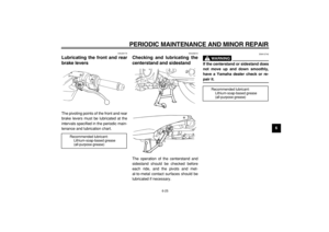
Checking the throttle cable
free play
The throttle cable free play should mea-
sure 3.0–5.0 mm (0.12–0.20 in) at the
throttle grip. Periodically check the
throttle cable free play and, if neces-
sary, have a Yamaha dealer adjust it.
EAU21401
Valve clearance
The valve clearance changes with use,
resulting in improper air-fuel mixture
and/or engine noise. To prevent this
from occurring, the valve clearance
must be adjusted by a Yamaha dealer
at the intervals specified in the periodic
maintenance and lubrication chart.
1. Idle adjusting screw
Engine idling speed:
1100–1300 r/min
1(a)
(b)
1. Throttle cable free play
1
Page 63 of 90

PERIODIC MAINTENANCE AND MINOR REPAIR
6-19
2
3
4
5
67
8
9
EAU33600
Tires
To maximize the performance, durabil-
ity, and safe operation of your vehicle,
note the following points regarding the
specified tires.
Tire air pressure
The tire air pressure should be checked
and, if necessary, adjusted before each
ride.
WARNING
EWA10500
�
The tire air pressure must be
checked and adjusted on cold
tires (i.e., when the temperature
of the tires equals the ambient
temperature).
�
The tire air pressure must be ad-
justed in accordance with the
riding speed and with the total
weight of rider, passenger, car-
go, and accessories approved
for this model.
WARNING
EWA11200
Because loading has an enormous
impact on the handling, braking,
performance and safety characteris-
tics of your vehicle, you should keep
the following precautions in mind.
�
NEVER OVERLOAD THE VEHI-
CLE! Operation of an overload-
ed vehicle may result in tire
damage, loss of control, or se-vere injury. Make sure that the
total weight of rider, passenger,
cargo, and accessories does
not exceed the specified maxi-
mum load for the vehicle.
�
Do not carry along loosely
packed items, which can shift
during a ride.
�
Securely pack the heaviest
items close to the center of the
vehicle and distribute the
weight evenly on both sides.
�
Adjust the tire air pressure with
regard to the load.
�
Check the tire condition and air
pressure before each ride.
Tire air pressure (measured on cold
tires):
0–90 kg (0–198 lb) :
Front:
225 kPa (33 psi) (2.25 kgf/cm
2
)
Rear:
250 kPa (36 psi) (2.50 kgf/cm
2
)
XP500 90–190 kg (198–419 lb)
XP500A 90–185 kg (198–408 lb) :
Front:
225 kPa (33 psi) (2.25 kgf/cm
2
)
Rear:
280 kPa (41 psi) (2.80 kgf/cm
2
)
Maximum load*:
XP500 190 kg (419 lb)
XP500A 185 kg (408 lb)
* Total weight of rider, passenger,
cargo and accessories
Page 64 of 90

PERIODIC MAINTENANCE AND MINOR REPAIR
6-20
1
2
3
4
5
6
7
8
9Tire inspection
The tires must be checked before each
ride. If the center tread depth reaches
the specified limit, if the tire has a nail or
glass fragments in it, or if the sidewall is
cracked, have a Yamaha dealer re-
place the tire immediately.
NOTE:
The tire tread depth limits may differ
from country to country. Always comply
with the local regulations.
Tire information
This model is equipped with tubeless
tires.
WARNING
EWA10470
�
Have a Yamaha dealer replace
excessively worn tires. Besides
being illegal, operating the vehi-
cle with excessively worn tires
decreases riding stability and
can lead to loss of control.
�
The replacement of all wheel
and brake related parts, includ-
ing the tires, should be left to a
Yamaha dealer, who has the
necessary professional knowl-
edge and experience.
1. Tire sidewall
2. Tire tread depth
Minimum tire tread depth (front and
rear):
1.6 mm (0.06 in)
12
Front tire:
Size:
120/70R14 M/C 55H
Manufacturer/model:
DUNLOP/D252F
BRIDGESTONE/TH01F
Rear tire:
Size:
160/60R15 M/C 67H
Manufacturer/model:
DUNLOP/D252
BRIDGESTONE/TH01R