Page 20 of 88

INSTRUMENT AND CONTROL FUNCTIONS
3-6
1
2
3
4
5
6
7
8
9
This tachometer unit is equipped with a
clock.
To set the clock:
1. Push both the “SELECT” and “RE-
SET” buttons for at least two sec-
onds.
2. When the hour digits start flashing,
push the “RESET” button to set the
hours.
3. Push the “SELECT” button to
change the minutes.
4. When the minute digits start flash-
ing, push the “RESET” button to
set the minutes.
5. Push the “SELECT” button to start
the clock.
NOTE:
�
After setting the clock, be sure to
push the “SELECT” button before
turning the key to “OFF”, otherwise
the clock will not be set.
�
When the key is turned to “OFF”,
the clock display will remain on for
48 hours and then go off to prevent
the battery from discharging.
EAU12181
Coolant temperature gauge
With the key in the “ON” position, the
coolant temperature gauge indicates
the temperature of the coolant. When
the key is turned to “ON”, the coolant
temperature gauge needle will sweep
once across the temperature range and
then return to “C” in order to test the
electrical circuit. The coolant tempera-
ture varies with changes in the weather
and engine load. If the needle reaches
or enters the red zone, stop the vehicle
and let the engine cool. (See
page 6-33.)
CAUTION:
ECA10020
Do not operate the engine if it is
overheated.
1. Coolant temperature gauge
2. Coolant temperature gauge red zone
12
Page 68 of 88

PERIODIC MAINTENANCE AND MINOR REPAIR
6-27
1
2
3
4
5
6
7
8
9
EAU23290
Checking the wheel bearings
The front and rear wheel bearings must
be checked at the intervals specified in
the periodic maintenance and lubrica-
tion chart. If there is play in the wheel
hub or if the wheel does not turn
smoothly, have a Yamaha dealer check
the wheel bearings.
EAU23370
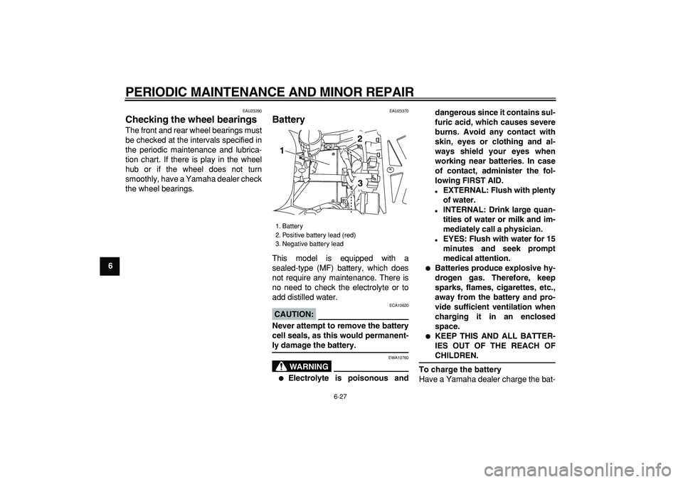
Battery
This model is equipped with a
sealed-type (MF) battery, which does
not require any maintenance. There is
no need to check the electrolyte or to
add distilled water.
CAUTION:
ECA10620
Never attempt to remove the battery
cell seals, as this would permanent-
ly damage the battery.
WARNING
EWA10760
�
Electrolyte is poisonous anddangerous since it contains sul-
furic acid, which causes severe
burns. Avoid any contact with
skin, eyes or clothing and al-
ways shield your eyes when
working near batteries. In case
of contact, administer the fol-
lowing FIRST AID.
�
EXTERNAL: Flush with plenty
of water.
�
INTERNAL: Drink large quan-
tities of water or milk and im-
mediately call a physician.
�
EYES: Flush with water for 15
minutes and seek prompt
medical attention.
�
Batteries produce explosive hy-
drogen gas. Therefore, keep
sparks, flames, cigarettes, etc.,
away from the battery and pro-
vide sufficient ventilation when
charging it in an enclosed
space.
�
KEEP THIS AND ALL BATTER-
IES OUT OF THE REACH OF
CHILDREN.
To charge the battery
Have a Yamaha dealer charge the bat-
1. Battery
2. Positive battery lead (red)
3. Negative battery lead
1
23
Page 82 of 88

SPECIFICATIONS
8-3
1
2
3
4
5
6
7
8
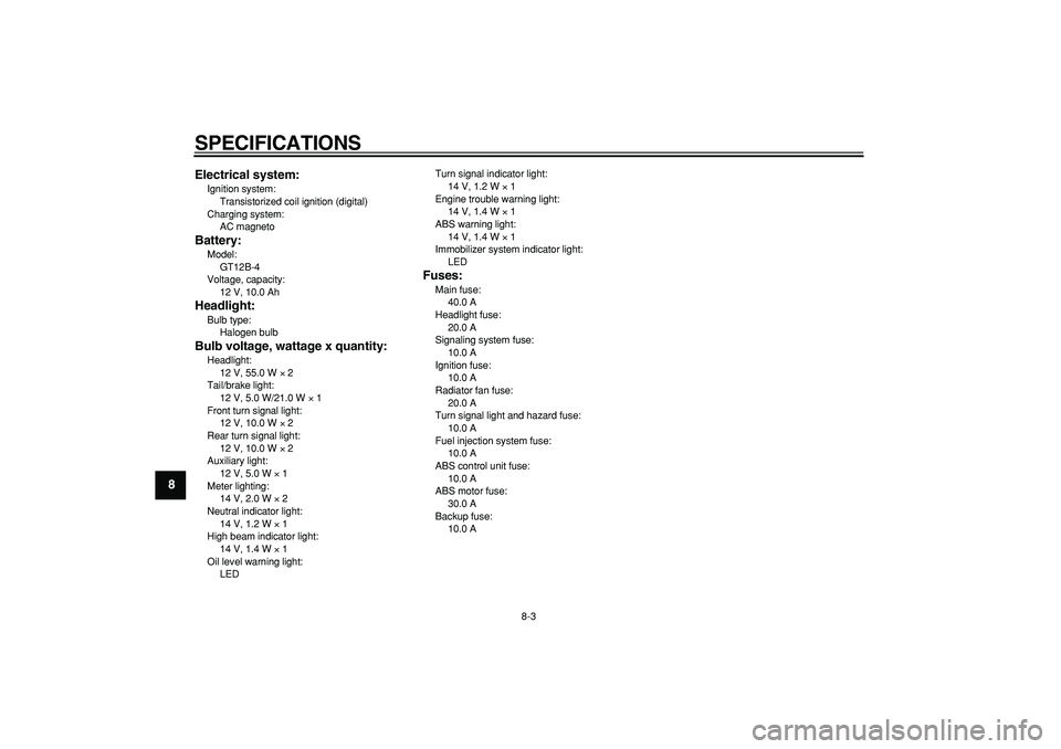
9Electrical system:
Ignition system:
Transistorized coil ignition (digital)
Charging system:
AC magneto
Battery:
Model:
GT12B-4
Voltage, capacity:
12 V, 10.0 Ah
Headlight:
Bulb type:
Halogen bulb
Bulb voltage, wattage x quantity:
Headlight:
12 V, 55.0 W
×
2
Tail/brake light:
12 V, 5.0 W/21.0 W
×
1
Front turn signal light:
12 V, 10.0 W
×
2
Rear turn signal light:
12 V, 10.0 W
×
2
Auxiliary light:
12 V, 5.0 W
×
1
Meter lighting:
14 V, 2.0 W
×
2
Neutral indicator light:
14 V, 1.2 W
×
1
High beam indicator light:
14 V, 1.4 W
×
1
Oil level warning light:
LEDTurn signal indicator light:
14 V, 1.2 W
×
1
Engine trouble warning light:
14 V, 1.4 W
×
1
ABS warning light:
14 V, 1.4 W
×
1
Immobilizer system indicator light:
LED
Fuses:
Main fuse:
40.0 A
Headlight fuse:
20.0 A
Signaling system fuse:
10.0 A
Ignition fuse:
10.0 A
Radiator fan fuse:
20.0 A
Turn signal light and hazard fuse:
10.0 A
Fuel injection system fuse:
10.0 A
ABS control unit fuse:
10.0 A
ABS motor fuse:
30.0 A
Backup fuse:
10.0 A