Page 78 of 106

4-9
E
EJU01355
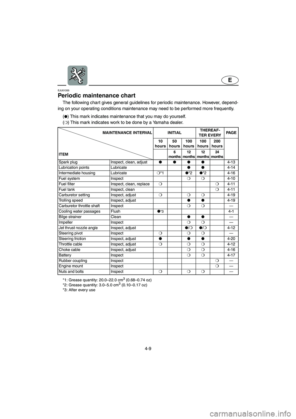
Periodic maintenance chart
The following chart gives general guidelines for periodic maintenance. However, depend-
ing on your operating conditions maintenance may need to be performed more frequently.
*1: Grease quantity: 20.0–22.0 cm3 (0.68–0.74 oz)
*2: Grease quantity: 3.0–5.0 cm3 (0.10–0.17 oz)
*3: After every use
(�) This mark indicates maintenance that you may do yourself.
(
❍) This mark indicates work to be done by a Yamaha dealer.
MAINTENANCE INTERVAL INITIALTHEREAF-
TER EVERYPA G E
10
hours50
hours100
hours 100
hours 200
hours
ITEM
6
months12
months12
months24
months
Spark plug Inspect, clean, adjust ����
4-13
Lubrication points Lubricate��
4-14
Intermediate housing Lubricate❍
*1�
*2�
*2 4-16
Fuel system Inspect❍❍
4-10
Fuel filter Inspect, clean, replace❍❍
4-11
Fuel tank Inspect, clean❍
4-11
Carburetor setting Inspect, adjust❍❍❍
4-19
Trolling speed Inspect, adjust��
4-19
Carburetor throttle shaft Inspect❍❍
—
Cooling water passages Flush�
*34-1
Bilge strainer Clean��
—
Impeller Inspect❍❍
—
Jet thrust nozzle angle Inspect, adjust�
/❍�
/❍
4-12
Steering pivot Inspect❍❍❍
—
Steering friction Inspect, adjust���
4-20
Throttle cable Inspect, adjust❍❍❍
4-12
Choke cable Inspect, adjust ❍❍
4-16
Battery Inspect❍❍
4-17
Rubber coupling Inspect❍
—
Engine mount Inspect❍
—
Nuts and bolts Inspect❍❍❍
—
UF1N73.book Page 9 Monday, May 10, 2004 10:37 AM
Page 79 of 106
4-10
E
EJU01383
Inspecting the fuel system
WARNING@ Gasoline is highly flammable and explo-
sive. A fire or explosion can cause
severe injury or death. Shut off the
engine. Do not smoke. Avoid spilling
gasoline.
@
Check the fuel system for leaks, cracks,
or malfunctions. If any problem is found, do
the necessary repair or replacement as
required. If repair is necessary, consult a
Yamaha dealer.
Check:
�Carburetor for leakage.
�Fuel pump for malfunction or leakage.
�Fuel tank for water or dirt.
�Fuel tank for damage, cracks or leakage.
�Fuel hose joint for leakage.
�Fuel hose for cracks or other damage.
�Fuel filter for leakage.
�Fuel cock for leakage.
�Air vent check valve for leakage.
�Fuel tank filler cap for damage.
WARNING@ Failure to check for and repair any fuel
leakage may result in fire or explosion.
@
UF1N73.book Page 10 Monday, May 10, 2004 10:37 AM
Page 82 of 106

4-13
E
EJU13431
Cleaning and adjusting the
spark plugs
The spark plug is an important engine
component and is easy to inspect. The con-
dition of the spark plug can indicate some-
thing about the condition of the engine. For
example, if the center electrode porcelain is
very white, this could indicate an intake air
leak or carburetion problem in that cylinder.
Do not attempt to diagnose any problems
yourself. Have a Yamaha dealer service the
watercraft.
Remove and inspect the spark plug peri-
odically; heat and deposits will cause the
spark plug to slowly break down and erode.
If electrode erosion becomes excessive, or if
carbon and other deposits are excessive,
replace the spark plug with the specified
plug.
Measure the spark plug gap a with a
wire thickness gauge. Replace the spark
plug or adjust the gap to specification if nec-
essary.
To install the spark plug:
1. Clean the gasket surface.
2. Wipe any dirt from the threads of the
spark plug.
3. Install the spark plug, and then tighten it
to the specified torque.
4. Install the spark plug cap.Standard spark plug: BR7HS
Spark plug gap:
0.6–0.7 mm (0.024–0.028 in)
Spark plug tightening torque:
25 N·m (2.5 kgf·m, 18 ft·lb)
UF1N73.book Page 13 Monday, May 10, 2004 10:37 AM
Page 88 of 106

4-19
E
EJU01109
Adjusting the carburetor
The carburetor is a vital part of the engine
and requires very sophisticated adjustment.
Most adjusting should be left to a Yamaha
dealer who has the professional knowledge
and experience to perform it. However, the
operator may adjust the trolling speed as
part of the usual maintenance routine.
CAUTION:@ The carburetor was set at the Yamaha
factory after many tests. If the settings
are disturbed by someone who does not
have the necessary technical knowledge,
poor engine performance and damage
may result.
@
EJU01303
Adjusting the trolling speed
1. Put the watercraft in the water.
2. Start the engine and warm it up for 1 or
2 minutes. Using a diagnostic tachome-
ter, adjust the engine speed to specifica-
tion.
3. Turn the throttle stop screw 1 clockwise
to increase engine speed if necessary.
Turn it counterclockwise to decrease
engine speed if necessary.
Trolling speed: 1,250–1,350 r/min
UF1N73.book Page 19 Monday, May 10, 2004 10:37 AM
Page 92 of 106

4-23
E
EJU01359
Specifications
*1: Pump Octane Number
*2: Research Octane NumberMODEL
ITEMUnit SJ700
WATERCRAFT CAPACITY
Maximum people on board Number of people 1
DIMENSIONS
Length mm (in) 2,240 (88.2)
Width mm (in) 680 (26.8)
Height mm (in) 660 (26.0)
Dry weight kg (lb) 132 (291)
PERFORMANCE
Maximum power output kW (PS) @ r/min 53.7 (73) @ 6,300
Maximum fuel consumption L/h (US gal/h, Imp gal/h) 29 (7.7, 6.4)
Cruising range at full throttle hr. 0.6
Trolling speed r/min 1,250–1,350
ENGINE
Engine type 2-stroke
Number of cylinders 2
Engine displacement
cm
3 (cu in)701 (42.78)
Bore & stroke mm (in) 81 ×
68 (3.19 ×
2.68)
Compression ratio 7.2
Lubrication system Pre-mixed fuel
Cooling system Water cooled
Starting system Electric starter
Ignition system CDI
Spark plug BR7HS (NGK)
Spark plug gap mm (in) 0.6–0.7 (0.024–0.028)
Battery capacity V-AH 12-19
Charging system Flywheel magneto
DRIVE UNIT
Propulsion system Jet pump
Jet pump type Axial flow, single stage
Impeller rotation Counterclockwise (viewed from rear)
Transmission Direct drive from engine
Jet thrust nozzle angle Degree 37, 41, 45, 49
FUEL AND OIL
Recommended fuel Regular unleaded gasoline
Minimum octane rating PON (*1)
RON (*2)86
90
Recommended engine oil YAMALUBE 2-W, or an equivalent NMMA-
certified TC-W3 marine oil
Fuel mixing ratio (fuel to oil) 50:1
Fuel tank capacity
Total L (US gal, Imp gal) 18 (4.8, 4.0)
Reserve L (US gal, Imp gal) 5.5 (1.45, 1.21)
UF1N73.book Page 23 Monday, May 10, 2004 10:37 AM
Page 94 of 106

5-1
E
EJU01116
Troubleshooting
If you have any trouble with your watercraft, use this section to check for the possible
cause.
If you cannot find the cause, or if the procedure for replacement or repair is not described
in this Owner’s/Operator’s Manual, have a Yamaha dealer perform the necessary service.
EJU01367
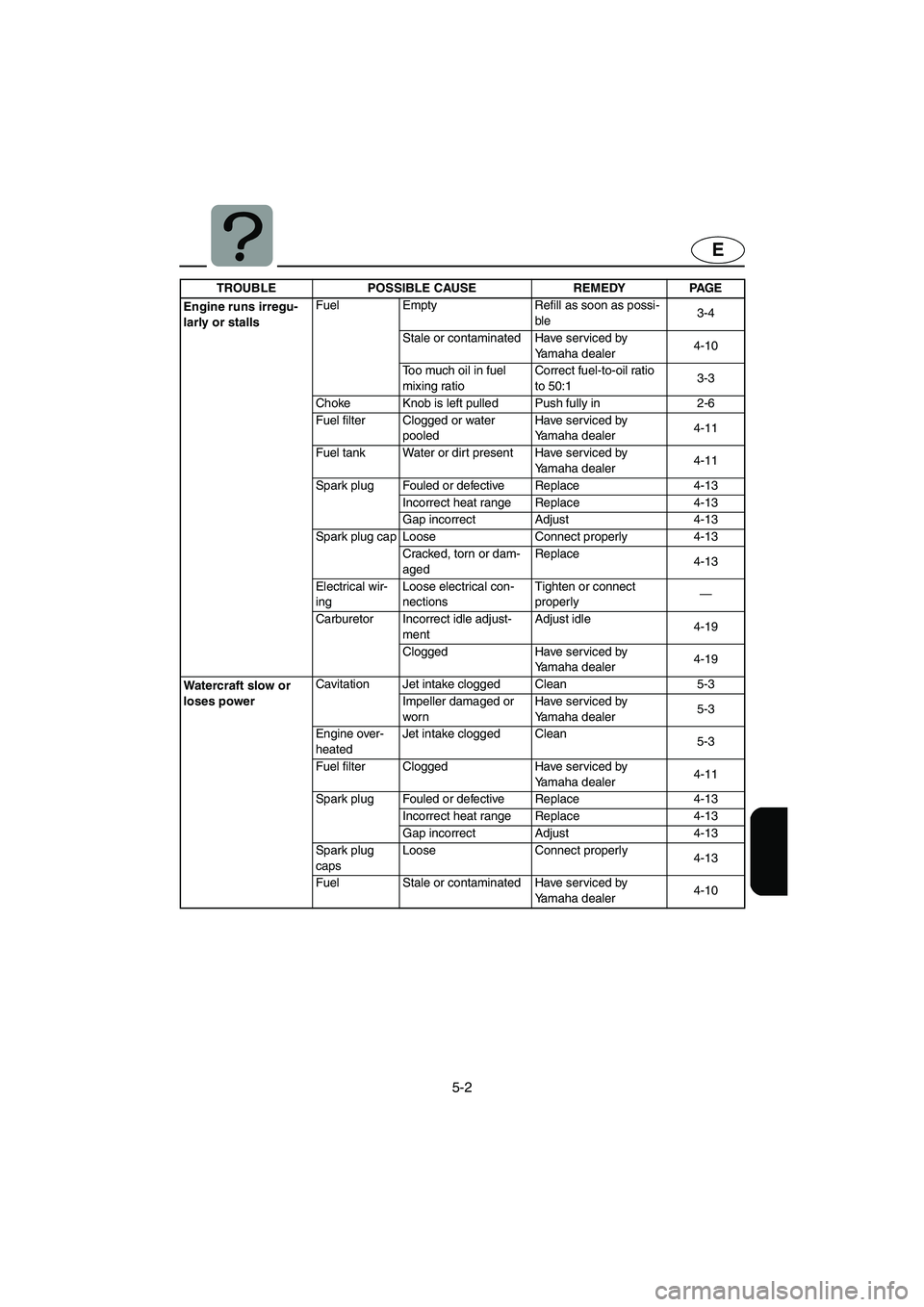
Troubleshooting chart
TROUBLE POSSIBLE CAUSE REMEDY PAGE
Engine does not
startStarter motor does not turn over
Engine shut-
off switch Clip not in place Install clip
2-5
Fuse Burned out Replace fuse and check
wiring4-20
Battery Run down Recharge 4-17
Poor terminal connec-
tionsTighten as required
4-17
Starter motor Faulty Have serviced by
Yamaha dealer—
Starter motor turns over
Fuel cock Turned to “OFF”Turn fuel cock knob to
“ON”2-4
Fuel Empty Refill as soon as possi-
ble3-4
Stale or contaminated Have serviced by
Yamaha dealer4-10
Fuel tank Water or dirt present Have serviced by
Yamaha dealer4-11
Spark plug Fouled or defective Clean or replace 4-13
Spark plug cap Not connected or loose Connect properly 4-13
Crankcase Filled with water Crank engine with plug
out until clean5-7
Fuel filter Clogged or water
pooledHave serviced by
Yamaha dealer4-11
Choke Knob moves back on
its ownTighten choke knob
adjusting nut4-16
UF1N73.book Page 1 Monday, May 10, 2004 10:37 AM
Page 95 of 106

5-2
E
Engine runs irregu-
larly or stallsFuel Empty Refill as soon as possi-
ble3-4
Stale or contaminated Have serviced by
Yamaha dealer4-10
Too much oil in fuel
mixing ratioCorrect fuel-to-oil ratio
to 50:13-3
Choke Knob is left pulled Push fully in 2-6
Fuel filter Clogged or water
pooledHave serviced by
Yamaha dealer4-11
Fuel tank Water or dirt present Have serviced by
Yamaha dealer4-11
Spark plug Fouled or defective Replace 4-13
Incorrect heat range Replace 4-13
Gap incorrect Adjust 4-13
Spark plug cap Loose Connect properly 4-13
Cracked, torn or dam-
agedReplace
4-13
Electrical wir-
ingLoose electrical con-
nectionsTighten or connect
properly—
Carburetor Incorrect idle adjust-
mentAdjust idle
4-19
Clogged Have serviced by
Yamaha dealer4-19
Wate rcr af t slow or
loses powerCavitation Jet intake clogged Clean 5-3
Impeller damaged or
wornHave serviced by
Yamaha dealer5-3
Engine over-
heatedJet intake clogged Clean
5-3
Fuel filter Clogged Have serviced by
Yamaha dealer4-11
Spark plug Fouled or defective Replace 4-13
Incorrect heat range Replace 4-13
Gap incorrect Adjust 4-13
Spark plug
capsLoose Connect properly
4-13
Fuel Stale or contaminated Have serviced by
Yamaha dealer4-10 TROUBLE POSSIBLE CAUSE REMEDY PAGE
UF1N73.book Page 2 Monday, May 10, 2004 10:37 AM
Page 96 of 106

5-3
E
EJU01118
Emergency procedures
EJU01119
Cleaning the jet intake and
impeller
If weeds or debris get caught in the intake
or impeller, cavitation can occur, causing jet
thrust to decrease even though engine
speed rises. If this condition is allowed to
continue, the engine will overheat and may
seize. If there is any sign that the jet intake
or impeller is clogged with weeds or debris,
beach the watercraft and check the intake
and impeller. Always stop the engine before
beaching the watercraft.
WARNING@ Before attempting to remove weeds or
debris from the jet intake or impeller
areas, shut the engine off and remove
the clip from the engine shut-off switch.
Severe injury or death could result from
contact with the rotating parts of the jet
pump.
@
1. Turn the watercraft on its side as shown.
CAUTION:@ �Place a suitable clean cloth or carpet-
ing underneath the watercraft to pro-
tect it from abrasions and scratches.
�Always turn the watercraft over onto
its port (left) side.
�When turning the watercraft on its
side, support the bow so the handle-
bars cannot be bent or damaged.
@
2. Remove any weeds or debris from
around the drive shaft, impeller, pump
housing, and jet thrust nozzle.
If debris is difficult to remove, consult
your Yamaha dealer.
UF1N73.book Page 3 Monday, May 10, 2004 10:37 AM