Page 86 of 324

’05 MATRIX_U (L/O 0409)
76
2005 MATRIX from Sep. ’04 Prod. (OM12892U)
The front passenger occupant classifica-
tion indicator light should indicate “OFF”
when the ignition key is in the “ON” posi-
tion and the child is in the child restraint
system after following these procedures.
The “OFF” indicator indicates the SRS
front passenger airbag and side airbag on
the passenger side will not deploy. If the
indicator light indicates “ON”, remove the
child restraint system and reinstall it with
the ignition key in the “ACC” or “LOCK”
position. If the indicator light still indicates
“ON” when the ignition key is turned to
the “ON” position, then the SRS front pas-
senger airbag and side airbag on the pas-
senger side may deploy in an accident.
Do not drive the vehicle in this condition.
Remove the child restraint system and
contact your Toyota dealer.CAUTION
�Never install a rear�facing child re-
straint system on the front passen-
ger seat. A forward�facing child re-
straint system should only be
installed on the front passenger
seat when unavoidable. If you must
install the child restraint system on
the front passenger seat, put the
seat in its most rearward position,
and install the forward�facing child
restraint system in the proper or-
der. Otherwise, the front passenger
occupant classification system can
not detect the presence of the child
restraint system and the front pas-
senger airbag and side airbag on
the front passenger seat could
deploy.
�Never install a rear�facing child re-
straint system on the front passen-
ger seat even if the front passenger
occupant classification indicator
light indicates “OFF”. In the event
of an accident, the impact of the
rapid inflation of the front passen-
ger airbag could cause death or se-
rious injury to the child if the rear�
facing child restraint system is
installed on the front passenger
seat.
Page 100 of 324

’05 MATRIX_U (L/O 0409)
90
2005 MATRIX from Sep. ’04 Prod. (OM12892U)
Adjust the mirror so that you can just
see the rear of your vehicle in the mir-
ror.
To reduce glare from the headlights of
the vehicle behind you during night
driving, operate the lever on the lower
edge of the mirror.
Daylight driving—Lever at position 1
The reflection in the mirror has greater
clarity at this position.
Night driving—Lever at position 2
Remember that by reducing glare you also
lose some rear view clarity.
CAUTION
Do not adjust the mirror while the
vehicle is moving. Doing so may
cause the driver to mishandle the ve-
hicle and an accident may occur re-
sulting in death or serious injuries.
Adjust the mirror so that you can just
see the rear of your vehicle in the mir-
ror.
This mirror is equipped with auto anti�
glare function. The function is designed
to reduce glare from the headlights of
the vehicle behind you during night
driving.
When the ignition key is inserted and
turned on, the inside rear view mirror al-
ways turns on in the automatic function
mode.
The indicator illuminates to show you that
the function is on.
Anti�glare inside rear view
mirrorAuto anti�glare inside rear
view mirror
Page 101 of 324

’05 MATRIX_U (L/O 0409)
91
2005 MATRIX from Sep. ’04 Prod. (OM12892U)
In automatic function mode, if the mirror
detects light from the headlights of the
vehicle behind you, the mirror surface
darkens slightly to reduce the reflected
light.
To turn off the automatic function, push
and release the “
” switch. The indica-
tor light will turn off.
To turn on the automatic function again,
push and release the “
” switch. The
indicator light will turn on.
Adjust it before driving so that the rear
view is in the best condition.
When the inside air temperature is low, it
may take a little longer for the mirror to
darken in response to the detection of
headlights.
CAUTION
Do not adjust the mirror while the
vehicle is moving. Doing so may
cause the driver to mishandle the ve-
hicle and an accident may occur re-
sulting in death or serious injuries.
To ensure correct functioning of an
anti�glare mirror sensors located on
both sides of the mirror, do not touch
or cover the sensors with your finger
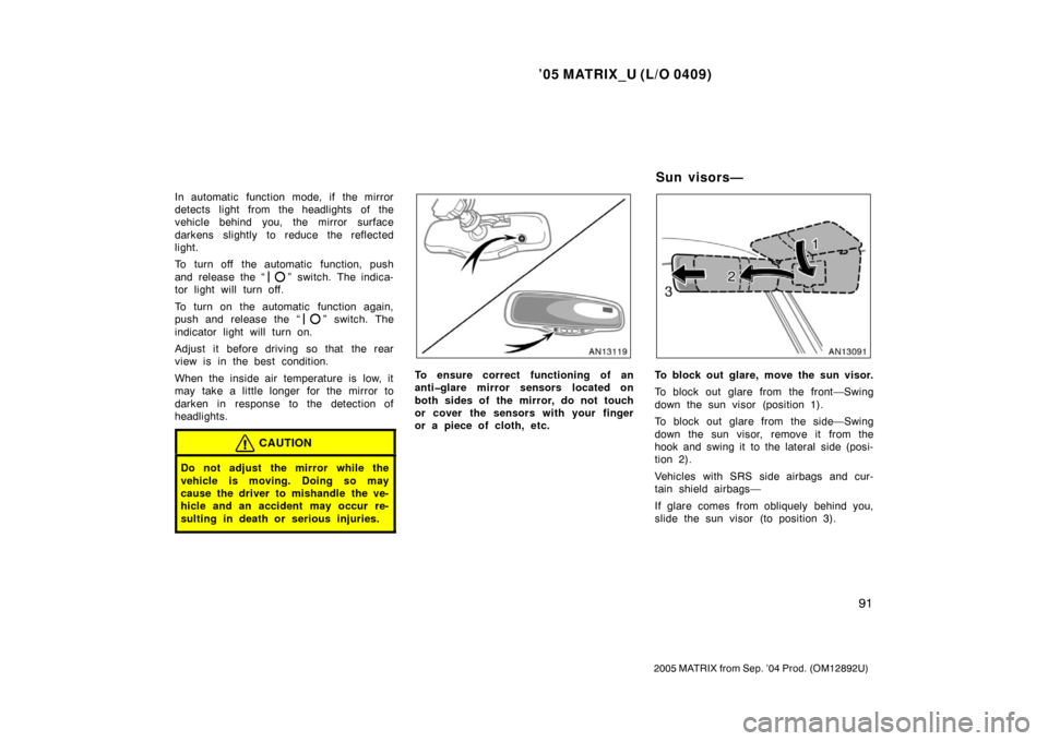
or a piece of cloth, etc.To block out glare, move the sun visor.
To block out glare from the front—Swing
down the sun visor (position 1).
To block out glare from the side—Swing
down the sun visor, remove it from the
hook and swing it to the lateral side (posi-
tion 2).
Vehicles with SRS side airbags and cur-
tain shield airbags—
If glare comes from obliquely behind you,
slide the sun visor (to position 3).
Su n viso rs—
Page 104 of 324

’05 MATRIX_U (L/O 0409)
94
2005 MATRIX from Sep. ’04 Prod. (OM12892U)
For the U.S.A.
For Canada
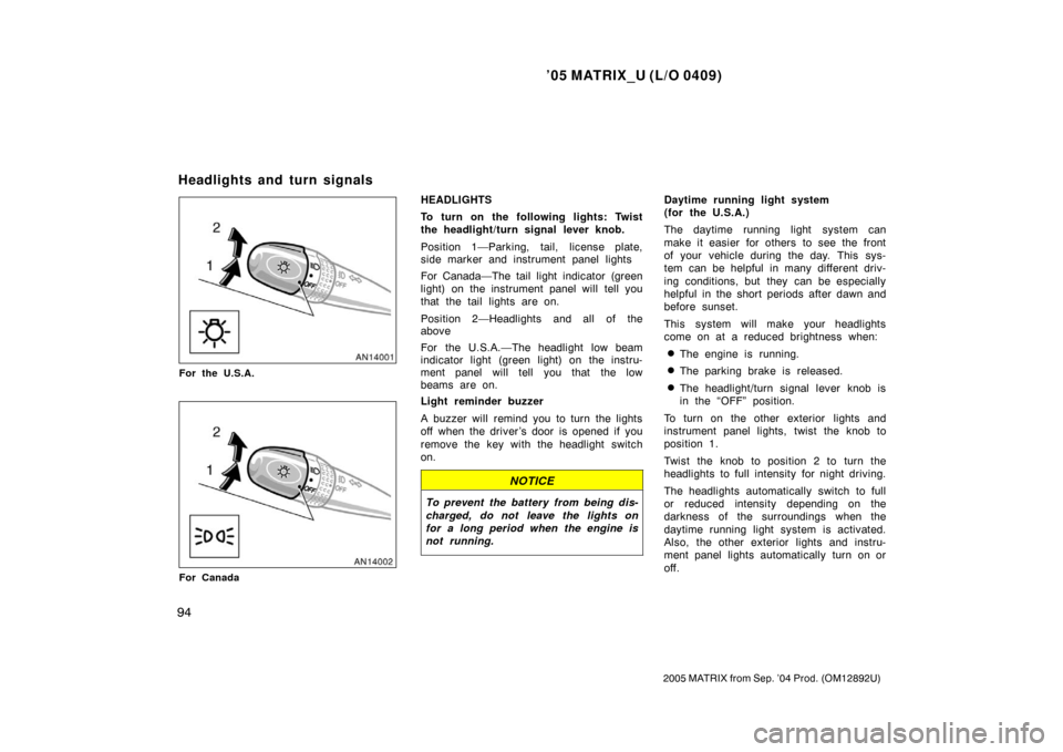
HEADLIGHTS
To turn on the following lights: Twist
the headlight/turn signal lever knob.
Position 1—Parking, tail, license plate,
side marker and instrument panel lights
For Canada—The tail light indicator (green
light) on the instrument panel will tell you
that the tail lights are on.
Position 2—Headlights and all of the
above
For the U.S.A.—The headlight low beam
indicator light (green light) on the instru-
ment panel will tell you that the low
beams are on.
Light reminder buzzer
A buzzer will remind you to turn the lights
off when the driver ’s door is opened if you
remove the key with the headlight switch
on.
NOTICE
To prevent the battery from being dis-
charged, do not leave the lights on
for a long period when the engine is
not running.
Daytime running light system
(for the U.S.A.)
The daytime running light system can
make it easier for others to see the front
of your vehicle during the day. This sys-
tem can be helpful in many different driv-
ing conditions, but they can be especially
helpful in the short periods after dawn and
before sunset.
This system will make your headlights
come on at a reduced brightness when:
�The engine is running.
�The parking brake is released.
�The headlight/turn signal lever knob is
in the “OFF” position.
To turn on the other exterior lights and
instrument panel lights, twist the knob to
position 1.
Twist the knob to position 2 to turn the
headlights to full intensity for night driving.
The headlights automatically switch to full
or reduced intensity depending on the
darkness of the surroundings when the
daytime running light system is activated.
Also, the other exterior lights and instru-
ment panel lights automatically turn on or
off.
Headlights and turn signals
Page 105 of 324

’05 MATRIX_U (L/O 0409)
95
2005 MATRIX from Sep. ’04 Prod. (OM12892U)
The daytime running light control sensor
is on the top of the driver’s side instru-
ment panel.
Do not place anything on the instrument
panel, and/or do not affix anything on the
windshield to block this sensor.Daytime running light system
(for Canada)
The daytime running light system can
make it easier for others to see the front
of your vehicle during the day. This sys-
tem can be helpful in many different driv-
ing conditions, but they can be especially
helpful in the short periods after dawn and
before sunset.
This system will make your headlights
come on at a reduced brightness when:
�The engine is running.
�The parking brake is released.
�The headligh
t/turn signal lever knob is
in the “OFF” position or position 1.
To turn on the other exterior lights and
instrument panel lights, twist the knob to
position 1.
Twist the knob to position 2 to turn the
headlights to full intensity for night driving.High�Low beams— For high beams, turn
the headlights on and push the lever away
from you (position 1). Pull the lever to-
ward you (position 2) for low beams.
The headlight high beam indicator light
(blue light) on the instrument panel will
tell you that the high beams are on.
Flashing the high beam headlights
(position 3)—Pull the lever all the way
back. The high beam headlights turn off
when you release the lever.
You can flash the high beam headlights
with the knob turned to “OFF”.
Page 106 of 324

’05 MATRIX_U (L/O 0409)
96
2005 MATRIX from Sep. ’04 Prod. (OM12892U)
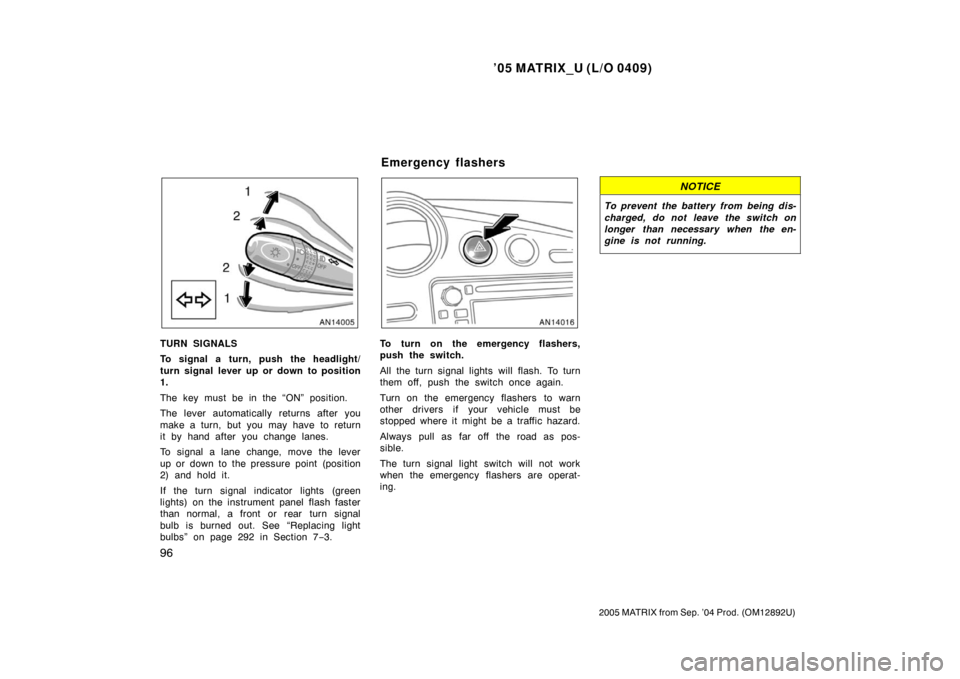
TURN SIGNALS
To signal a turn, push the headlight/
turn signal lever up or down to position
1.
The key must be in the “ON” position.
The lever automatically returns after you
make a turn, but you may have to return
it by hand after you change lanes.
To signal a lane change, move the lever
up or down to the pressure point (position
2) and hold it.
If the turn signal indicator lights (green
lights) on the instrument panel flash faster
than normal, a front or rear turn signal
bulb is burned out. See “Replacing light
bulbs” on page 292 in Section 7−3.To turn on the emergency flashers,
push the switch.
All the turn signal lights will flash. To turn
them off, push the switch once again.
Turn on the emergency flashers to warn
other drivers if your vehicle must be
stopped where it might be a traffic hazard.
Always pull as far off the road as pos-
sible.
The turn signal light switch will not work
when the emergency flashers are operat-
ing.
NOTICE
To prevent the battery from being dis-
charged, do not leave the switch on
longer than necessary when the en-
gine is not running.
Emergency flashers
Page 111 of 324
’05 MATRIX_U (L/O 0409)
101
2005 MATRIX from Sep. ’04 Prod. (OM12892U)
To defog or defrost the rear window,
push the switch.
The key must be in the “ON” position.
The thin heater wires on the inside of the
rear window will quickly clear the window
surface. An indicator light will illuminate to
indicate the defogger is operating.
Push the switch once again to turn the
defogger off.
The system will automatically shut off af-
ter the defogger have operated about 15
minutes.
Make sure you turn the defogger off when
the window is clear. Leaving the defogger
on for a long time could cause the battery
to discharge, especially during stop−and−
go driving. The defogger is not designed
for drying rain water or for melting snow.
NOTICE
When cleaning the inside of the rear
window, be careful not to scratch or
damage the heater wires or connec-
tors.
Page 113 of 324
’05 MATRIX_U (L/O 0409)
103
2005 MATRIX from Sep. ’04 Prod. (OM12892U)
OPERATION OF INSTRUMENTS AND
CONTROLS
Gauges, Meters and Service reminder indicators
Fuel gauge104
. . . . . . . . . . . . . . . . . . . . . . . . . . . . . . . . . . . . .\
. . . . . . . . . . .
Engine coolant temperature gauge 104
. . . . . . . . . . . . . . . . . . . . . . . . . . .
Tachometer 105
. . . . . . . . . . . . . . . . . . . . . . . . . . . . . . . . . . . . \
. . . . . . . . . . . .
Odometer and two trip meters 106
. . . . . . . . . . . . . . . . . . . . . . . . . . . . . . . .
Outside temperature display 106
. . . . . . . . . . . . . . . . . . . . . . . . . . . . . . . . .
Service reminder indicators and warning buzzers 107
. . . . . . . . . . . . . .
SECTION 1� 6