2005 SUZUKI SWIFT Solenoid
[x] Cancel search: SolenoidPage 18 of 1496
Downloaded from www.Manualslib.com manuals search engine 00-13 Precautions:
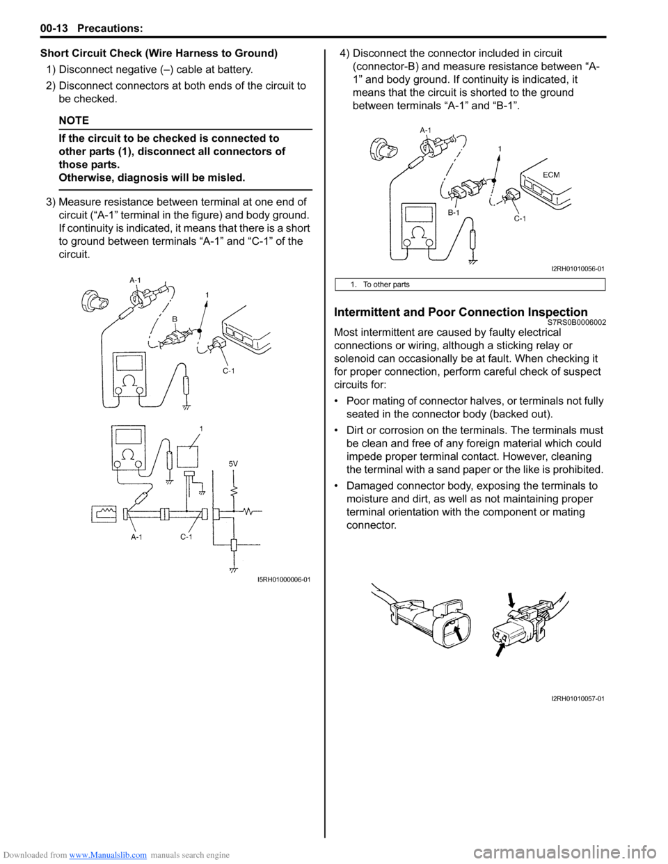
Short Circuit Check (Wire Harness to Ground)1) Disconnect negative (–) cable at battery.
2) Disconnect connectors at bot h ends of the circuit to
be checked.
NOTE
If the circuit to be checked is connected to
other parts (1), disconnect all connectors of
those parts.
Otherwise, diagnosis will be misled.
3) Measure resistance between terminal at one end of circuit (“A-1” terminal in the figure) and body ground.
If continuity is indicated, it means that there is a short
to ground between terminals “A-1” and “C-1” of the
circuit. 4) Disconnect the connector included in circuit
(connector-B) and measure resistance between “A-
1” and body ground. If continuity is indicated, it
means that the circuit is shorted to the ground
between terminals “A-1” and “B-1”.
Intermittent and Poor Connection InspectionS7RS0B0006002
Most intermittent are caused by faulty electrical
connections or wiring, although a sticking relay or
solenoid can occasionally be at fault. When checking it
for proper connection, perfor m careful check of suspect
circuits for:
• Poor mating of connector halves, or terminals not fully seated in the connector body (backed out).
• Dirt or corrosion on the terminals. The terminals must be clean and free of any foreign material which could
impede proper terminal contact. However, cleaning
the terminal with a sand paper or the like is prohibited.
• Damaged connector body, exposing the terminals to moisture and dirt, as well as not maintaining proper
terminal orientation with the component or mating
connector.
I5RH01000006-01
1. To other parts
I2RH01010056-01
I2RH01010057-01
Page 22 of 1496
Downloaded from www.Manualslib.com manuals search engine 0A-1 General Information:
General Information
General Information
General Description
AbbreviationsS7RS0B0101001
A:
ABDC: After Bottom Dead Center
ABS: Anti-lock Brake System
AC: Alternating Current
A/C: Air Conditioning
A-ELR: Automatic-Emergency Locking Retractor
A/F: Air Fuel Mixture Ratio
ALR: Automatic Locking Retractor
API: American Petroleum Institute
APP sensor: Accelerator Pedal Position Sensor
A/T: Automatic Transmission , Automatic Transaxle
AT D C : After Top Dead Center
ATF: Automatic Transmission Fluid, Automatic
Transaxle Fluid
B:
B+: Battery Positive Voltage
BBDC: Before Bottom Dead Center
BCM: Body Electrical Control Module
BDC: Bottom Dead Center
BTDC: Before Top Dead Center
C:
CAN: Controller Area Network
CKT: Circuit
CKP Sensor: Crankshaft Position Sensor
CMP Sensor: Camshaft Position Sensor
CO: Carbon Monoxide
CPP Switch: Clutch Pedal Position Switch (Clutch
Switch, Clutch Start Switch)
CPU: Central Processing Unit
CRS: Child Restraint System
D:
DC: Direct Current
DLC: Data Link Connector (Assembly Line Diag. Link,
ALDL, Serial Data Link, SDL)
DOHC: Double Over Head Camshaft
DOJ: Double Offset Joint
DRL: Daytime Running Light
DTC: Diagnostic Trouble Code (Diagnostic Code)
E:
EBCM: Electronic Brake Cont rol Module, ABS Control
Module
EBD: Electronic Brake Force Distribution
ECM: Engine Control Module
ECT Sensor: Engine Coolant Temperature Sensor (Water Temp. Sensor, WTS)
EFE Heater: Early Fuel Evaporation Heater (Positive
Temperature Coefficient, PTC Heater)
EGR: Exhaust Gas Recirculation
EGRT Sensor: EGR Temperature Sensor (Recirculated
Exhaust Gas Temp. Sensor, REGTS)
ELR: Emergency Locking Retractor
ESP ®: Electronic Stability Program
EPS: Electronic Power Steering
EVAP: Evaporative Emission EVAP Canister:
Evaporative Emission Canister
(Charcoal Canister)
F:
4WD: 4 Wheel
Drive
G:
GEN: Generator
GND: Ground
GPS: Global Positioning System
H:
HVAC: Heating, Ventilating and Air Conditioning
HC: Hydrocarbons
HO2S: Heated Oxygen Sensor
I:
IAC Valve: Idle Air Control Valve (Idle Speed Control
Solenoid Valve, ISC Solenoid Valve)
IAT Sensor: Intake Air Temperature Sensor (Air
temperature Sensor, ATS)
ICM: Immobilizer Control Module
IG: Ignition
ISC Actuator: Idle Speed Control Actuator
L:
LH: Left Hand
LHD: Left Hand Drive Vehicle
LSPV: Load Sensing Proportioning Valve
M:
MAF Sensor: Mass Air Flow Sensor (Air Flow Sensor, AFS, Air Flow Meter, AFM)
MAP Sensor: Manifold Absolute Pressure Sensor
(Pressure Sensor, PS)
Max: Maximum
MFI: Multiport Fuel Injection (Mu ltipoint Fuel Injection)
Min: Minimum
MIL: Malfunction Indicator Lamp (“SERVICE ENGINE
SOON” Light)
M/T: Manual Transmission, Manual Transaxle
N:
NOx: Nitrogen Oxides
O:
OBD: On-Board Diagnostic System (Self-Diagnosis
Function)
O/D: Overdrive
OHC: Over Head Camshaft
O2S: Oxygen Sensor
P:
PCM: Powertrain Control Module
PCV: Positive Crankcase Ventilation
PNP: Park / Neutral Position
P/S: Power Steering
PSP Switch: Power Steering Pressure Switch (P/S
Pressure Switch)
R:
RH: Right Hand
RHD: Right Hand Drive Vehicle
S:
SAE: Society of Automotive Engineers
Page 302 of 1496

Downloaded from www.Manualslib.com manuals search engine 1D-17 Engine Mechanical:
Engine Assembly Removal and InstallationS7RS0B1406011
NOTE
After replacing electric throttle body
assembly, perform calibration of throttle
valve referring to “Electric Throttle Body
System Calibration in Section 1C”.
Removal1) Relieve fuel pressure according to “Fuel Pressure Relief Procedure in Section 1G”.
2) Disconnect negative and pos itive cable at battery.
3) Remove battery and tray.
4) Remove engine hood after disconnecting windshield washer hose.
5) Remove right and left side engine under covers.
6) Remove A/C compressor belt by referring to “Compressor Drive Belt Remo val and Installation in
Section 7B” or “Compressor Drive Belt Removal and
Installation in Section 7B”.
7) Drain engine oil, transaxle oil and coolant.
8) Remove cowl top plate referring to “Cowl Top Components in Section 9K”.
9) Remove air cleaner assembly referring to “Air Cleaner Components”.
10) With hose connected, detach A/C compressor from its bracket (A/C model) referring to “Compressor
Assembly Removal and Installation in Section 7B” or
“Compressor Assembly Removal and Installation in
Section 7B”.
CAUTION!
Suspend removed A/C compressor at a place
where no damage will be caused during
removal and installation of engine assembly.
11) Remove intake manifold rear stiffener (1) from intake manifold and cylinder block. 12) Disconnect the following electric wires:
• MAP sensor (1)
• ECT sensor (2)
•EGR valve (3)
• CMP sensor (4)
• Electric throttle body assembly (5)
• Ignition coil assembly (6)
• Injectors (7)
• Heated oxygen sensor No. 2 (8) and No. 1 (9)
• Oil control valve (10)
• Engine oil pressure switch (11)
• CKP sensor (12)
• Knock sensor (13)
• Back up light switch (14)
• Generator (15)
• Starting motor (16)
• Ground terminal (17) from intake manifold
• Battery ground terminal (18) from exhaust manifold
• Battery ground cable (19) from transaxle
• Magnet clutch switch of A/C compressor (A/C model)
• Each wire harness clamps
• Output shaft speed sensor (VSS) (34) (A/T model)
• Solenoid valve (33) (A/T model)
• Transmission range sensor (32) (A/T model)
• Input shaft speed sensor (31) (A/T model)
13) Remove fuse box from its bracket.
14) Disconnect the following cables: • Gear select control cable (23) (M/T model)
• Gear shift control cable (24) (M/T model)
• A/T select cable (A/T model)
15) Disconnect the following hoses: • Brake booster hose (26) from intake manifold
• Radiator inlet and outlet hoses (20) from each pipe
• Heater inlet and outlet hoses (21) from each pipe
• Fuel feed hoses (22) from fuel feed pipe
• EVAP canister purge valve hose (30) from purge pipe
• A/T fluid cooler hoses (A/T model)
16) With hose connected, detach clutch operating cylinder (25). (M/T model)
CAUTION!
Suspend removed clutch operating cylinder
at a place where no damage will be caused
during removal and installation of engine
assembly.
1
I6RS0B141014-01
Page 496 of 1496

Downloaded from www.Manualslib.com manuals search engine 4-ii Table of Contents
Repair Instructions ..............................................4D-2Parking Brake Inspection and Adjustment ..........4D-2
Parking Brake Cable Removal and Installation ......................................................... 4D-3
Parking Brake Lever Removal and Installation ....4D-3
Specifications .... ...................................................4D-4
Tightening Torque Specifications ........................4D-4
ABS ........................................... .................4E-1
Precautions........................................................... 4E-1
Precautions in Diagnosing Troubles ................... 4E-1
Precautions in On-Vehicle Service...................... 4E-1
Precautions in Hydraulic Unit Operation Check ................................................................ 4E-1
General Description ............................................. 4E-2 ABS Description .................................................. 4E-2
ABS Hydraulic Unit / Control Module Assembly Description ....................................... 4E-2
CAN Communication System Description........... 4E-3
Schematic and Routing Diagram ........................ 4E-4 ABS Schematic ................................................... 4E-4
ABS Wiring Circuit Diagram ................................ 4E-5
Component Location ........... ................................ 4E-7
ABS Components Location ................................. 4E-7
Front Wheel Speed Sensor Components Location ............................................................ 4E-7
Rear Wheel Speed Sensor Components Location ............................................................ 4E-8
Diagnostic Information and Procedures ............ 4E-8 ABS Check .......................................................... 4E-8
ABS Warning Light Check................................. 4E-10
EBD Warning Light (Brake Warning Light) Check .............................................................. 4E-10
DTC Check........................................................ 4E-11
DTC Table ......................................................... 4E-11
DTC Clearance ................................................. 4E-12
Scan Tool Data ................................................. 4E-12
ABS Warning Light Does Not Come ON at Ignition Switch ON .......................................... 4E-13
ABS Warning Light Comes ON Steady ............. 4E-14
EBD Warning Light (Brake Warning Light) Comes ON Steady .......................................... 4E-15
Serial Data Link Circuit Check .......................... 4E-16
DTC C1021, C1022 / C1025, C1026 / C1031, C1032 / C1035, C1036: Right-Front / Left-
Front / Right-Rear / Left-Rear Wheel Speed
Sensor Circuit or Sensor Ring ........................ 4E-18
DTC C1041 / C1045 / C1051 / C1055, DTC C1042 / C1046 / C1052 / C1056: Right-Front
/ Left-Front / Right-Rear / Left-Rear Inlet
Solenoid Circuit, Right-Front / Left-Front /
Right-Rear / Left-Rear Outlet Solenoid
Circuit .............................................................. 4E-20
DTC C1057: Power Source Circuit ................... 4E-21
DTC C1061: ABS Pump Motor and/or Motor Driver Circuit ................................................... 4E-22
DTC C1063: Solenoid Valve Power Supply Driver Circuit ................................................... 4E-23
DTC C1071: ABS Control Module..................... 4E-24 DTC U1073: Control Module Communication
Bus Off ............................................................ 4E-25
DTC U1100: Lost Communication with ECM (Reception Error)............................................. 4E-27
Repair Instructions ............ ................................ 4E-28
ABS Hydraulic Unit Operati on Check................ 4E-28
ABS Hydraulic Unit / Control Module
Assembly Components ...... ............................. 4E-29
ABS Hydraulic Unit / Control Module
Assembly On-Vehicle Inspection .................... 4E-29
ABS Hydraulic Unit / Control Module
Assembly Removal and Inst allation ................ 4E-29
Front / Rear Wheel Speed Sensor On-Vehicle Inspection ........................................................ 4E-31
Front Wheel Speed Sensor Removal and Installation ....................................................... 4E-32
Front Wheel Speed Sensor Inspection ............. 4E-32
Rear Wheel Speed Sensor Removal and Installation ....................................................... 4E-33
Rear Wheel Speed Sensor Inspection .............. 4E-34
Front Wheel Encoder On-Veh icle Inspection .... 4E-34
Front wheel Enco der Removal and
Installation ....................................................... 4E-34
Rear Wheel Encoder On-Veh icle Inspection..... 4E-34
Rear Wheel Encoder Removal and Installation ....................................................... 4E-34
Specifications ..................... ................................ 4E-35
Tightening Torque Specifications ...................... 4E-35
Special Tools and Equipmen t ........................... 4E-35
Special Tool ...................................................... 4E-35
Electronic Stability Prog ram ...................4F-1
Precautions ........................................................... 4F-1
Precautions in Diagnosing Troubles ................... 4F-1
Precautions in On-Vehicle Service...................... 4F-1
Precautions in Hydraulic Unit Operation Check ................................................................ 4F-1
Precautions in Sensor Calibration ....................... 4F-1
Precautions in Speedometer Test or Other Tests ................................................................. 4F-2
General Description ............................................. 4F-2 Electronic Stability Program Description ............. 4F-2
Electronic Stability Program Construction ........... 4F-3
ESP® Hydraulic Unit / Control Module
Assembly Description........................................ 4F-5
Warning Lamp, Indicator Lamp Description ........ 4F-6
CAN Communication System Description........... 4F-6
CAN Communication System For Electronic Stability Program Description ............................ 4F-7
Schematic and Routing Diagram ........................ 4F-8 Electronic Stability Program Schematic .............. 4F-8
Electronic Stability Program Wiring Circuit Diagram............................................................. 4F-9
Component Location ............ ............................. 4F-11
Electronic Stability Program Component
Location........................................................... 4F-11
Diagnostic Information and Procedures .......... 4F-12 Electronic Stability Program System Check ...... 4F-12
ESP® Warning lamp Check .............................. 4F-14
Page 497 of 1496
Downloaded from www.Manualslib.com manuals search engine Table of Contents 4-iii
ABS Warning Lamp Check ............................... 4F-14
EBD Warning Lamp (Brake Warning Lamp) Check .............................................................. 4F-15
DTC Check ....................................................... 4F-15
DTC Table ......................................................... 4F-15
DTC Clearance ................................................. 4F-18
Fail-Safe Table ................ .................................. 4F-19
Scan Tool Data ................................................. 4F-20
Visual Inspection ............................................... 4F-21
ESP ® Warning Lamp Does Not Come ON at
Ignition Switch ON .......................................... 4F-21
ESP ® Warning Lamp Comes ON Steady......... 4F-22
ABS Warning Lamp Does Not Come ON at Ignition Switch ON .......................................... 4F-23
ABS Warning Lamp Comes ON Steady............ 4F-24
EBD Warning Lamp (Brake Warning Lamp) Comes ON Steady .......................................... 4F-24
Serial Data Link Circuit Check .......................... 4F-26
DTC C1016: Stop Lamp Swit ch Circuit Failure .. 4F-28
DTC C1017 / C1023: Yaw Rate / G Sensor Assembly Failure ............................................ 4F-29
DTC C1018: Brake Fluid Le vel Switch Failure .. 4F-30
DTC 1020: Master Cylinder Pressure Sensor Power Supply Failure ...................................... 4F-31
DTC C1021, C1022 / C1025, C1026 / C1031, C1032 / C1035, C1036: Wheel Speed
Sensor Circuit or Encode r Failure ................... 4F-32
DTC C1024: Steering Angle Sensor Circuit
Failure ............................................................. 4F-34
DTC C1027: ESP ® OFF Switch Circuit
Failure ............................................................. 4F-34
DTC C1028: Master Cylinder Pressure Sensor Circuit Failure ....... .............................. 4F-35
DTC C1034: Yaw Rate / G Sensor Assembly Power Supply Failure ...................................... 4F-36
DTC C1037: Steering Angle Sensor Power Supply Failure ................................................. 4F-37
DTC C1038: Steering Angle Sensor Detect Rolling Counter Fa ilure from ESP® Control
Module ............................................................ 4F-38
DTC C1039: Yaw Rate / G Sensor Assembly Internal Failure .............. .................................. 4F-39
DTC C1040: Stability Control System Function Failure .............................................. 4F-39
DTC C1041 / C1042 / C1043 / C1044 / C1045 / C1046 / C1051 / C1052 / C1053 / C1054 /
C1055 / C1056: Solenoid Circuit Failure ......... 4F-40
DTC C1057: ESP ® Control Module Power
Supply Circuit Failure .... .................................. 4F-41
DTC C1061: Pump Motor and/or Motor Driver Circuit Failure .................................................. 4F-42
DTC C1063: Solenoid Valve Power Supply Driver Circuit Failure ....................................... 4F-43
DTC 1071: ESP ® Control Module Internal
Defect.............................................................. 4F-44 DTC C1073: Lost Communication With Yaw
Rate / G Sensor Assembly .............................. 4F-45
DTC C1075 / 1076 / 1078: Sensor Calibration Incomplete.......................... ............................. 4F-46
DTC C1090: Invalid Communication with
ECM ................................................................ 4F-47
DTC C1091 / C1094: ECM Data in CAN Line Failure / Invalid Torque Control
Communication with ECM .. ............................. 4F-48
DTC U1073: Control Module Communication Bus Off ............................................................ 4F-49
DTC U1100: Lost Communication with ECM (Reception Error)............................................. 4F-50
DTC U1126: Lost Communication with Steering Angle Sensor (Reception Error)........ 4F-51
DTC U1140: Lost Communication with BCM (Reception Error)............................................. 4F-52
Repair Instructions ........... ................................. 4F-54
ESP® Hydraulic Unit Operation Check ............. 4F-54
Sensor Calibration............................................. 4F-54
ESP® Hydraulic Unit / Control Module
Assembly On-Vehicle Inspection .................... 4F-55
ESP ® Hydraulic
Unit / Control Module
Assembly Removal and Inst allation ................ 4F-56
Front / Rear Wheel Speed Sensor On-Vehicle Inspection ........................................................ 4F-57
Front Wheel Speed Sensor Removal and Installation ....................................................... 4F-58
Front Wheel Speed Sensor Inspection ............. 4F-59
Rear Wheel Speed Sensor Removal and Installation ....................................................... 4F-59
Rear Wheel Speed Sensor Inspection .............. 4F-60
Front Wheel Encode r On-Vehicle Inspection .... 4F-61
Front Wheel Encoder Removal and Installation ....................................................... 4F-61
Rear Wheel Encoder On-Veh icle Inspection..... 4F-61
Rear Wheel Encoder Removal and Installation ....................................................... 4F-61
Master Cylinder Pressure Sensor On-Vehicle
Inspection ........................................................ 4F-61
Yaw Rate / G Sensor Assembly On-Vehicle Inspection ........................................................ 4F-62
Yaw Rate / G Sensor Assembly Removal and Installation ....................................................... 4F-63
Yaw Rate / G Sensor Inspection ....................... 4F-64
Steering Angle Sensor On-Vehicle Inspection .. 4F-64
Steering Angle Sensor Removal and Installation ....................................................... 4F-65
Steering Angle Sensor Inspection ..................... 4F-65
ESP® OFF Switch Removal an d Installation .... 4F-65
ESP® OFF Switch Inspection ........................... 4F-65
Specifications .................... ................................. 4F-66
Tightening Torque Specifications ...................... 4F-66
Special Tools and Equipmen t ........................... 4F-66
Special Tool ...................................................... 4F-66
Page 541 of 1496
Downloaded from www.Manualslib.com manuals search engine ABS: 4E-2
General Description
ABS DescriptionS7RS0B4501001
The ABS (Antilock Brake System) controls the fluid
pressure applied to the wheel cylinder of each brake
from the master cylinder so that each wheel is not locked
even when hard braking is applied.
This ABS has also the following function.
While braking is applied, but before ABS control
becomes effective, braking force is distributed between
the front and rear so as to prevent the rear wheels from
being locked too early for better stability of the vehicle.
The main component parts of this ABS include the
following parts in addition to those of the conventional
brake system.
• Wheel speed sensor which senses revolution speed of each wheel and outputs its signal.
• ABS warning light which light s to inform abnormality
when system fails to operate properly.
• ABS hydraulic unit / cont rol module assembly is
incorporated ABS co ntrol module, ABS hydraulic unit
(actuator assembly), solenoid valve power supply
driver (transistor), solenoid valve driver (transistor),
pump motor driver (transistor).
– ABS control module which sends operation signal to ABS hydraulic unit to control fluid pressure
applied to each wheel cylinder based on signal
from each wheel speed sensor so as to prevent
wheel from locking.
– ABS hydraulic unit which operates according to signal from ABS control module to control fluid
pressure applied to wheel cylinder of each 4
wheels.
– Solenoid valve power supp ly driver (transistor)
which supplies power to solenoid valve in ABS
hydraulic unit.
– Solenoid valve driver (transistor) which controls each solenoid valves in ABS hydraulic unit.
– Pump motor driver (transistor) which supplies power to pump motor in ABS hydraulic unit.
This ABS is equipped with Electronic Brake force
Distribution (EBD) system that controls a fluid pressure
of rear wheels to best condition, which is the same
function as that of proportion ing valve, by the signal from
wheel sensor independently of change of load due to
load capacity and so on. An d if the EBD system fails to
operate properly, the brake warning light lights to inform
abnormality.
ABS Hydraulic Unit / Control Module Assembly
Description
S7RS0B4501002
ABS control module is a component of ABS hydraulic
unit / control module asse mbly and has the following
functions.
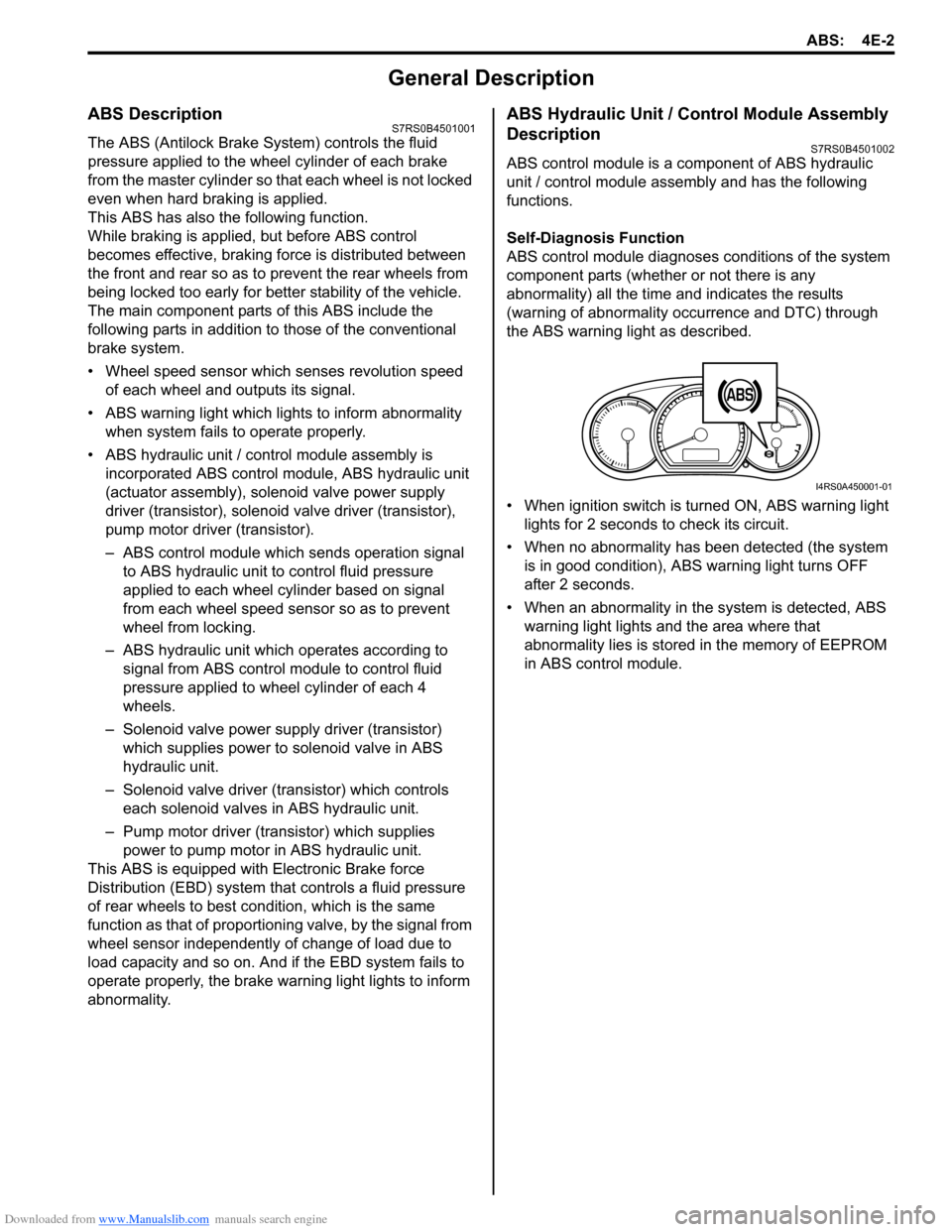
Self-Diagnosis Function
ABS control module diagnose s conditions of the system
component parts (whether or not there is any
abnormality) all the time and indicates the results
(warning of abnormality occurrence and DTC) through
the ABS warning light as described.
• When ignition switch is turned ON, ABS warning light lights for 2 seconds to check its circuit.
• When no abnormality has been detected (the system is in good condition), ABS warning light turns OFF
after 2 seconds.
• When an abnormality in th e system is detected, ABS
warning light lights and the area where that
abnormality lies is stored in the memory of EEPROM
in ABS control module.
1
I4RS0A450001-01
Page 543 of 1496
Downloaded from www.Manualslib.com manuals search engine ABS: 4E-4
Schematic and Routing Diagram
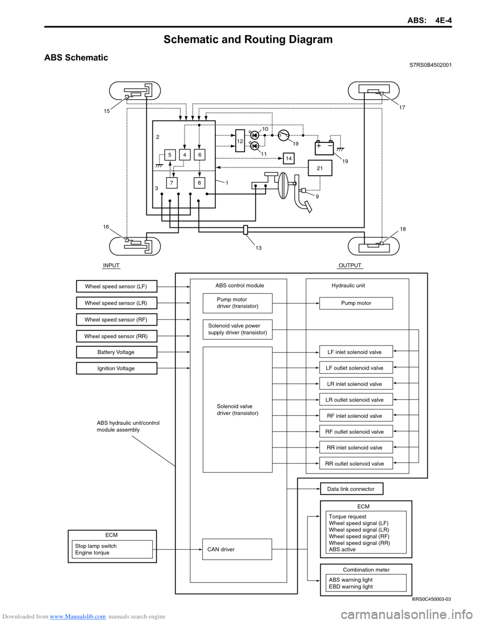
ABS SchematicS7RS0B4502001
INPUTOUTPUT
ABS control moduleWheel speed sensor (LF)
Wheel speed sensor (LR)
Wheel speed sensor (RF)Battery Voltage
Ignition Voltage
Pump motor
driver (transistor)
Solenoid valve power
supply driver (transistor)
Solenoid valve
driver (transistor) Hydraulic unit
Pump motor
LF inlet solenoid valve
LF outlet solenoid valve
LR inlet solenoid valve
LR outlet solenoid valve
RF inlet solenoid valve
RF outlet solenoid valve
RR inlet solenoid valve
RR outlet solenoid valve
Data link connector
ABS hydraulic unit/control
module assembly
Wheel speed sensor (RR)
3 7
2
645
8 12
14
21
15
16
1
13
18
17
19
19
11
10
9
CAN driverStop lamp switch
Engine torque
ECM
ABS warning light
EBD warning light
Combination meter
Torque request
ECMWheel speed signal (LF)
Wheel speed signal (LR)
Wheel speed signal (RF)
Wheel speed signal (RR)
ABS active
I6RS0C450003-03
Page 544 of 1496
Downloaded from www.Manualslib.com manuals search engine 4E-5 ABS:
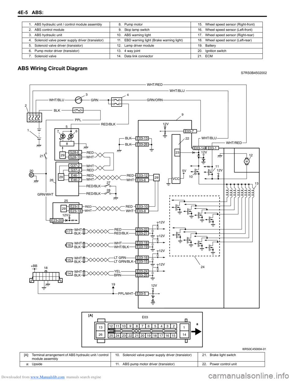
ABS Wiring Circuit DiagramS7RS0B4502002
1. ABS hydraulic unit / control module assembly 8.
Pump motor 15. Wheel speed sensor (Right-front)
2. ABS control module 9. Stop lamp switch 16. Wheel speed sensor (Left-front)
3. ABS hydraulic unit 10. ABS warning light 17. Wheel speed sensor (Right-rear)
4. Solenoid valve power supply driver (transistor) 11. EBD warnin g light (Brake warning light) 18. Wheel speed sensor (Left-rear)
5. Solenoid valve driver (transistor) 12. Lamp driver module 19. Battery
6. Pump motor driver (transistor) 13. 4 way joint 20. Ignition switch
7. Solenoid valve 14. Data link connector 21. ECM
[A]
14
1516171819202122232425 1
23456789101112
13
26 E03
a
WHT/BLU
BLKWHT/BLU
M
12V
9
10 11 12
13
BLKE03-14E03-1
E03-13
E03-26
YELBRN
14E03-24
LT GRN/BLKLT GRN
15
WHTWHT/BLK
16
RED
WHTBLK
WHTBLK
WHTBLK
WHTBLKRED/BLK
17
12V
PPL/WHT
18E03-5
1912V
5V
12V
23
24
VCC22
E03-25
E03-15E03-16
E03-19E03-18
E03-22E03-21
WHT/RED
WHT/RED
+BB
GRN/ORN
E03-7
WHT/BLUGRN
1
2
3
4
8
RED/BLK
E03-12
E03-6
RED
WHTE03-10E03-8
REDWHT
20 7
6
529
29
G28-8
G28-10
25
29
E23-3E23-18
GRN/WHT
21
PPL
12V
E23-20
12V
12V
12V
12V
REDWHTE46-1
E46-2
BLK
RED/BLK
RED/BLK
RED
RED
WHT
WHT
27
28
26
29
G37-2
G37-4
REDWHT
I6RS0C450004-01
[A]: Terminal arrangement of ABS hydraulic unit / control module assembly 10. Solenoid valve power supply driver
(transistor) 21. Brake light switch
a: Upside 11. ABS pump motor driver (transistor) 22. Power control unit