2005 SUZUKI SWIFT bracket
[x] Cancel search: bracketPage 811 of 1496

Downloaded from www.Manualslib.com manuals search engine Automatic Transmission/Transaxle: 5A-167
Specifications
Tightening Torque SpecificationsS7RS0B5107001
NOTE
The specified tightening torque is also described in the following.
“Select Cable Components”
“Automatic Transaxle Unit Components”
“Automatic Transaxle Assembly Components”
“Oil Pump Assembly Components”
“Transaxle Rear Cover (O/D and 2nd Coast Brake Piston) Assembly Components”
“Valve Body Assembly Components”
“Differential Assembly Components”
Reference:
For the tightening torque of fastener not specified in this section, refer to “Fasteners Information in Section 0A”.
Fastening part
Tightening torque
Note
N ⋅mkgf-mlb-ft
A/T fluid drain plug 171.7 12.5 �) / �) / �)
Transmission range sensor bolt 5.5 0.55 4.0�) / �)
Output shaft speed sensor bolt 131.3 9.5 �) / �)
Input shaft speed sensor bolt 5.5 0.55 4.0�)
Valve body harness connector bolt 7.00.7 5.0 �)
Shift solenoid bolt 111.1 8.0 �)
Oil strainer bolt 101.0 7.5 �) / �)
Oil pan bolt 7.00.7 5.0 �) / �)
Transaxle and engine fastening bolt and nut 85 8.5 61.5�)
Drive plate to torque converter bolt 252.5 18.0 �)
Transaxle stiffener bolt 555.5 40�)
Starter motor bolt and nut 505.0 36.5 �)
Oil pump subassembly bolt 101.0 7.5 �)
Rear cover plug 7.5 0.75 5.5�)
Solenoid valve bolt 111.1 8.0 �)
Final gear bolt 787.8 56.5 �)
Torque converter housing plug 7.5 0.75 5.5�)
Lubrication tube clamp bolt 5.5 0.55 4.0�)
Fluid reservoir RH plate bolt 5.5 0.55 4.0�)
Torque converter housing bolt 292.9 21�) / �) / �)
Manual detent spring bolt 101.0 7.5 �)
Parking lock pawl bracket bolt 7.5 0.75 5.5�)
Rear cover bolt 252.5 18.0 �)
Fluid reservoir LH plate bolt 101.0 7.5 �)
Oil pump assembly bolt 252.5 18.0 �)
Transaxle case plug 7.5 0.75 5.5�)
Valve body harness connector bolt 5.5 0.55 4.0�)
Valve body bolt 111.1 8.0 �)
Fluid outlet union 252.5 18.0 �)
Fluid cooler pipe union bolt 222.2 16.0 �)
Fluid cooler pipe bracket bolt 101.0 7.5 �)
Fluid filler tube bolt 101.0 7.5 �)
Input shaft speed sensor bolt 111.1 8.0 �)
Harness bracket bolt 232.3 17.0 �)
Select cable clamp bolt 101.0 7.5 �)
Transmission range sensor lock nut 70.7 5.0 �)
Manual select lever nut 131.3 9.5 �)
Engine mounting LH bracket bolt 555.5 40.0
�)
Page 819 of 1496

Downloaded from www.Manualslib.com manuals search engine Manual Transmission/Transaxle: 5B-5
Gear Shift Control Lever and Cable ComponentsS7RS0B5206003
1
3
4
(a)
7
A
(b)5
A
111 2
10
(c)
9
6
8 2
I7RS0A521001-03
1. Gear shift control lever knob 9. Cable bracket
2. Cable bracket bolt 10. Clip
Be sure to direct claw of clip to M/T side as shown in figure.
3. Gear shift lever boot 11. To gear shift control lever assembly
4. Gear shift control cable : Apply grease 99000-25011 to cable end. 12. To M/T
5. Gear select control cable : Apply grease 99000-25011 to cable end. : 13 N
⋅m (1.3 kgf-m, 9.5 lb-ft)
6. Gear shift control lever assembly mounting nut : 10 N⋅m (1.0 kgf-m, 7.5 lb-ft)
7. Gear shift control lever assembly : 55 N⋅m (5.5 kgf-m, 40.0 lb-ft)
8. Cable grommet bolt : Do not reuse.
Page 822 of 1496
![SUZUKI SWIFT 2005 2.G Service Workshop Manual Downloaded from www.Manualslib.com manuals search engine 5B-8 Manual Transmission/Transaxle:
Manual Transaxle Unit ComponentsS7RS0B5206008
13
6(a)
5
14(c)
114 7
(b)
12
7(b)
8
2
5 [A]
1
10
6
(a)
(a)
( SUZUKI SWIFT 2005 2.G Service Workshop Manual Downloaded from www.Manualslib.com manuals search engine 5B-8 Manual Transmission/Transaxle:
Manual Transaxle Unit ComponentsS7RS0B5206008
13
6(a)
5
14(c)
114 7
(b)
12
7(b)
8
2
5 [A]
1
10
6
(a)
(a)
(](/manual-img/20/7607/w960_7607-821.png)
Downloaded from www.Manualslib.com manuals search engine 5B-8 Manual Transmission/Transaxle:
Manual Transaxle Unit ComponentsS7RS0B5206008
13
6(a)
5
14(c)
114 7
(b)
12
7(b)
8
2
5 [A]
1
10
6
(a)
(a)
(b)3
9
9
(b)
(d)
I6RS0C520004-03
[A]: Forward
7. Engine left mounting bracket bolt and nuts 14. Clutch operating cylinder bolt
1. Engine 8. Clutch housing lower plate : 85 N⋅m (8.5 kgf-m, 61.5 lb-ft)
2. Transaxle 9. Engine rear mounting bracket bolts : 55 N⋅m (5.5 kgf-m, 40.0 lb-ft)
3. Engine rear mounting and bracket 10. Transaxle to engine nut : 23 N⋅m (2.3 kgf-m, 17.0 lb-ft)
4. Back up light switch connector 11. Ground cable : 11 N⋅m (1.1 kgf-m, 8.0 lb-ft)
5. Clutch operating cylinder 12. Engine left mounting bracket
6. Transaxle to engine bolt 13. Gear shift & select control cables
Page 824 of 1496

Downloaded from www.Manualslib.com manuals search engine 5B-10 Manual Transmission/Transaxle:
16) Remove engine under covers.
17) Support transaxle with transmission jack.
18) Remove transaxle to engine bolts and nut of lower side.
19) Remove engine left mounting (1) with bracket (2).
20) Remove engine rear mounting bracket bolts (1).
21) Remove other attached parts from transaxle, if any.
22) Pull transaxle so as to disconnect input shaft from clutch disc, and then lower it. Remounting
CAUTION!
• Care should be taken not to scratch oil
seal lip with drive shaft while raising
transaxle.
• Do not hit drive shaft joint with hammer when installing it into differential gear.
Reverse dismounting procedure for remounting noting
the following.
• Tighten each bolts and nuts to specified torque referring to “Manual Transaxle Unit Components”.
• Set each clamp for wiring securely.
• Fill transaxle oil referring to “Manual Transaxle Oil
Change”.
• Fill coolant referring to “Cooling System Flush and
Refill in Section 1F”.
• Install hook (1) and ground cable (2) at specified position as shown in figure.
• Connect battery and check function of engine, clutch
and transaxle.
1
2
I4RS0A520021-01
1
I4RS0A520022-01
3. Transaxle side cover 4. Transaxle left case
90
1
2 3
4
I4RS0A520023-01
Page 825 of 1496

Downloaded from www.Manualslib.com manuals search engine Manual Transmission/Transaxle: 5B-11
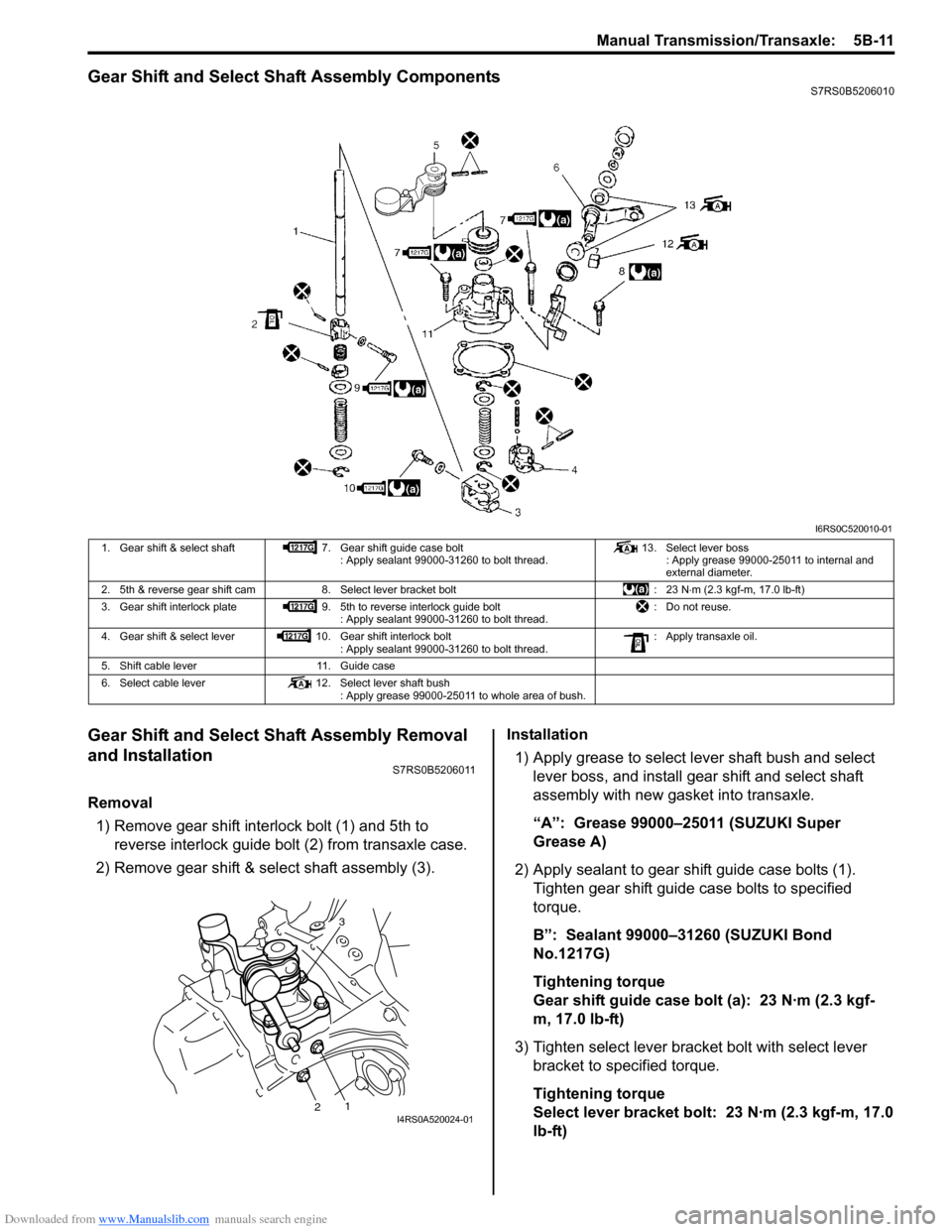
Gear Shift and Select Shaft Assembly ComponentsS7RS0B5206010
Gear Shift and Select Shaft Assembly Removal
and Installation
S7RS0B5206011
Removal1) Remove gear shift interlock bolt (1) and 5th to reverse interlock guide bolt (2) from transaxle case.
2) Remove gear shift & select shaft assembly (3). Installation
1) Apply grease to select lever shaft bush and select lever boss, and install gear shift and select shaft
assembly with new gasket into transaxle.
“A”: Grease 99000–25011 (SUZUKI Super
Grease A)
2) Apply sealant to gear shift guide case bolts (1). Tighten gear shift guide case bolts to specified
torque.
B”: Sealant 99000–31260 (SUZUKI Bond
No.1217G)
Tightening torque
Gear shift guide case bolt (a): 23 N·m (2.3 kgf-
m, 17.0 lb-ft)
3) Tighten select lever brac ket bolt with select lever
bracket to specified torque.
Tightening torque
Select lever bracket bolt: 23 N·m (2.3 kgf-m, 17.0
lb-ft)
I6RS0C520010-01
1. Gear shift & select shaft 7. Gear shift guide case bolt
: Apply sealant 99000-31260 to bolt thread. 13. Select lever boss
: Apply grease 99000-25011 to internal and
external diameter.
2. 5th & reverse gear shift cam 8. Select lever bracket bolt : 23 N⋅m (2.3 kgf-m, 17.0 lb-ft)
3. Gear shift interlock plate 9. 5th to reverse interlock guide bolt
: Apply sealant 99000-31260 to bolt thread. : Do not reuse.
4. Gear shift & select lever 10. Gear shift interlock bolt
: Apply sealant 99000-31260 to bolt thread. : Apply transaxle oil.
5. Shift cable lever 11. Guide case
6. Select cable lever 12. Select lever shaft bush
: Apply grease 99000-25011 to whole area of bush.
3
12I4RS0A520024-01
Page 849 of 1496

Downloaded from www.Manualslib.com manuals search engine Manual Transmission/Transaxle: 5B-35
6) Hold differential assembly with soft jawed vise (3),
install final gear (2) as shown in figure and then
tighten bolts (1) to specified torque.
CAUTION!
Use of any other bolts than specified ones is
prohibited.
Tightening torque
Final gear bolt (a): 90 N·m (9.0 kgf-m, 65.0 lb-ft)
Specifications
Tightening Torque SpecificationsS7RS0B5207001
NOTE
The specified tightening torque is also described in the following.
“Gear Shift Control Leve r and Cable Components”
“Manual Transaxle Unit Components”
“Gear Shift and Select Shaft Assembly Components”
“Manual Transaxle Assembly Components”
“Gear Shift Shaft Components”
“Differential Components”
Reference:
For the tightening torque of fastener not specified in this section, refer to “Fasteners Information in Section 0A”.
I4RS0A520043-01
Fastening part Tightening torque
Note
N ⋅mkgf-mlb-ft
Transaxle oil drain plug 21 2.1 15.5 �)
Transaxle oil level / filler plug 21 2.1 15.5 �)
Back up light switch 23 2.3 17.0 �)
Gear shift guide case bolt 23 2.3 17.0 �)
Select lever bracket bolt 23 2.3 17.0 �)
Gear shift interlock bolt 23 2.3 17.0 �)
5th to reverse interlock guide bolt 23 2.3 17.0 �)
Countershaft nut 100 10.0 72.5 �)
Shift fork bolt 10 1.0 7.5 �)
Side cover bolt 10 1.0 7.5 �)
Reverse gear shift lever bolt 23 2.3 17.0 �)
Reverse shaft bolt 23 2.3 17.0 �)
Transaxle case bolt 23 2.3 17.0 �)
Side bearing retainer bolt 23 2.3 17.0 �)
Gear shift locating bolt 13 1.3 9.5 �)
Left case plate bolt 23 2.3 17.0 �)
Oil gutter bolt 10 1.0 7.5 �)
Final gear bolt 90 9.0 65.0 �)
Page 856 of 1496

Downloaded from www.Manualslib.com manuals search engine 5C-4 Clutch:
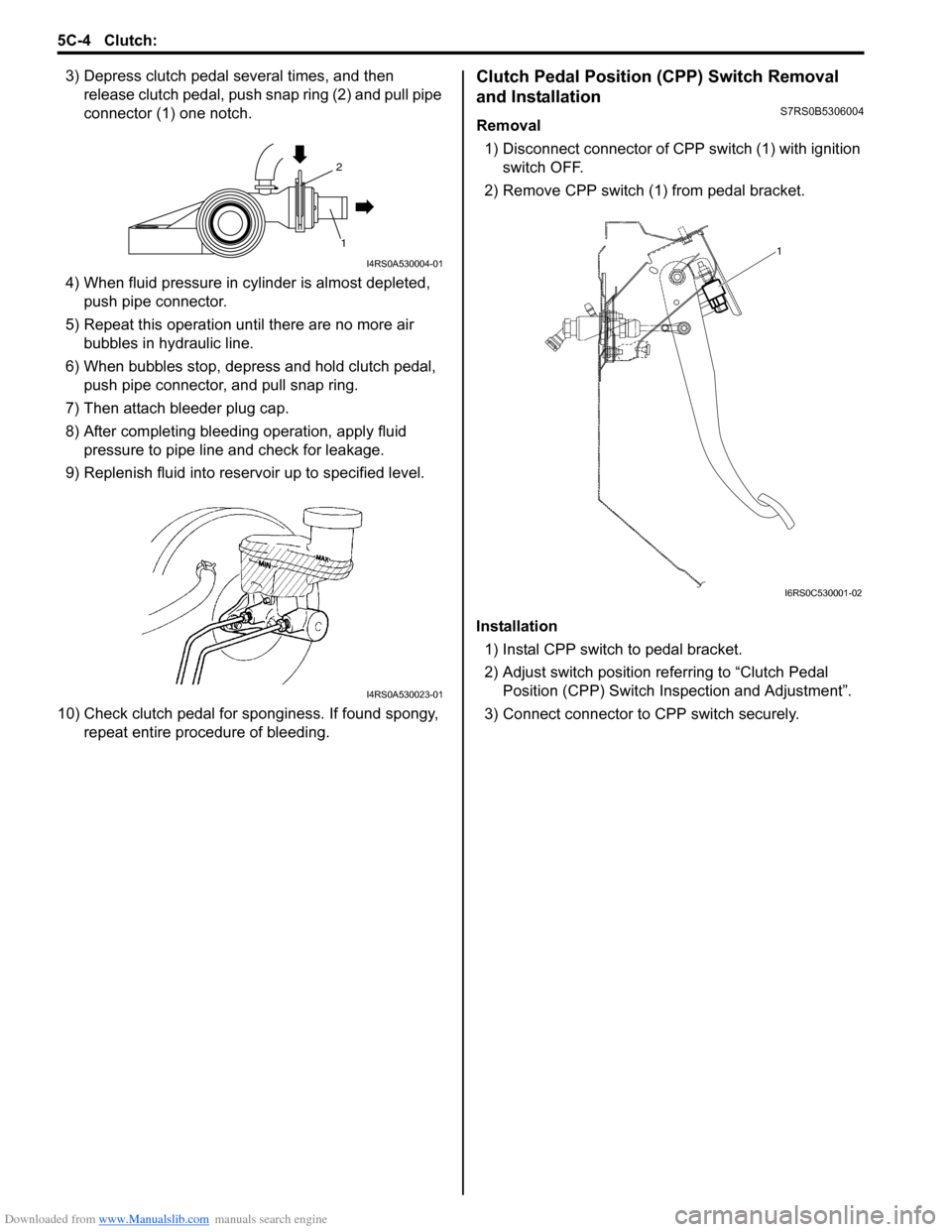
3) Depress clutch pedal several times, and then release clutch pedal, push snap ring (2) and pull pipe
connector (1) one notch.
4) When fluid pressure in cylinder is almost depleted, push pipe connector.
5) Repeat this operation until there are no more air bubbles in hydraulic line.
6) When bubbles stop, depress and hold clutch pedal, push pipe connector, and pull snap ring.
7) Then attach bleeder plug cap.
8) After completing bleeding operation, apply fluid pressure to pipe line and check for leakage.
9) Replenish fluid into reserv oir up to specified level.
10) Check clutch pedal for sponginess. If found spongy, repeat entire procedure of bleeding.Clutch Pedal Position (CPP) Switch Removal
and Installation
S7RS0B5306004
Removal
1) Disconnect connector of C PP switch (1) with ignition
switch OFF.
2) Remove CPP switch (1 ) from pedal bracket.
Installation 1) Instal CPP switch to pedal bracket.
2) Adjust switch position re ferring to “Clutch Pedal
Position (CPP) Switch Inspection and Adjustment”.
3) Connect connector to CPP switch securely.
2
1
I4RS0A530004-01
I4RS0A530023-01
1
I6RS0C530001-02
Page 859 of 1496

Downloaded from www.Manualslib.com manuals search engine Clutch: 5C-7
Clutch Operating Cylinder Removal and
Installation
S7RS0B5306010
Removal1) Clean around brake master cylinder reservoir cap and take out fluid with syringe or such from brake
master cylinder reservoir.
2) Disconnect clutch fluid pipe (2) from operating cylinder referring to “Clutch Fluid Pipe Removal and
Installation”.
3) Remove clutch operating cylinder (1).
Installation
Reverse removal procedure for installation noting the
following. • Apply grease to push rod tip.
“A”: Grease 99000–25100 (SUZUKI Silicone
Grease)
• Tighten clutch operating cylinder bolt to specified torque.
Tightening torque
Clutch operating cylinder bolt: 23 N·m (2.3 kgf-
m, 17.0 lb-ft)
Clutch Operating Cylinder InspectionS7RS0B5306011
Check operating cylinder for damage and fluid leakage.
If malfunction is found, repl ace clutch operating cylinder.
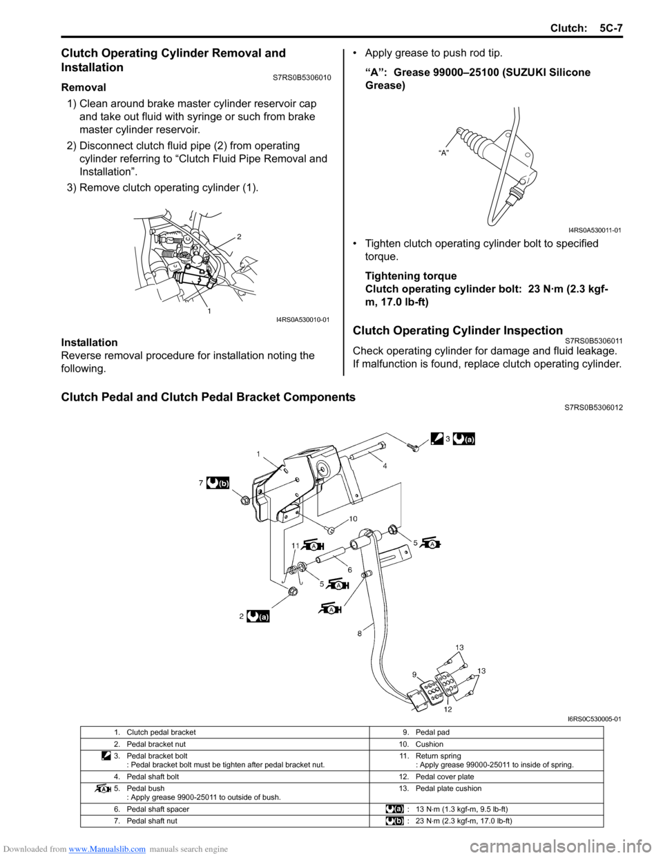
Clutch Pedal and Clutch Pedal Bracket ComponentsS7RS0B5306012
2
1I4RS0A530010-01
“A”
I4RS0A530011-01
I6RS0C530005-01
1. Clutch pedal bracket 9. Pedal pad
2. Pedal bracket nut 10. Cushion
3. Pedal bracket bolt : Pedal bracket bolt must be tighten after pedal bracket nut. 11. Return spring
: Apply grease 99000-25011 to inside of spring.
4. Pedal shaft bolt 12. Pedal cover plate
5. Pedal bush : Apply grease 9900-25011 to outside of bush. 13. Pedal plate cushion
6. Pedal shaft spacer : 13 N⋅m (1.3 kgf-m, 9.5 lb-ft)
7. Pedal shaft nut : 23 N⋅m (2.3 kgf-m, 17.0 lb-ft)